background image

Bullet Tower

 24VAC / 50Hz 


www.lancerbeverage.com 

Page 8 of 34 

Hoshizaki Lancer reserve the right to change specifications without notice. 

Part No: 68000028 

Images are for illustration purposes only as product may vary. 

No 061-2  -  17 December 2019 

3.6  Connecting Syrup & Soda / Water Lines 

  This dispenser is designed to be supported by a remote chiller system and connected to 

the cooling system via an insulated post mix Python. 

  Connect the syrup; soda supply and return (or water if applicable) tube tails of the Bullet 

Tower to the supply lines from the Python using standard installation procedures. 

  The soda (or water if applicable) supply is continuously circulated between the chiller and 

tower ensuring the beverage is dispensed at the required temperature. 

  Use a tube cutter to cut tubing. Tubing cut with a saw will result in plastic shavings that 

could plug the flow controls in the dispensing valve. 

  Ensure the lines from python to the Tower connections are insulated to prevent 

condensation. 


3.7  Electrical Connections 

  Connect the LEV valve and the Top Logo LED Lights electrical supply wires to the 

secondary output of a 24VAC transformer. 

  For Illuminated Towers connect the 24VDC to 24VDC convertor wires to the secondary 

output of the 24VAC transformer. 

  (Lancer Transformer 83000451, 240 to 24Vac 3A is sold separately and is suitable for 

supplying up to 3 towers). 

  Plug the transformer into a 240VAC 50 Hz outlet, protected by an appropriate circuit 

breaker and Residual Current Device (RCD).  

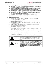
  Illuminated Bullet Tower colour adjustment: 


The Acrylic Tube colour can be changed by the LED controller changing the colour of the 

LED Assembly at the base of the tower. 


Point the remote control supplied at the sensor attached to the LED controller and press 

the required colour button on the remote. 


Important: Cover the sensors on any other Bullet Towers close by as the remote will affect 

any LED controller within its range. 


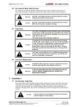
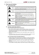
Warning 

If the transformer is damaged, they must be replaced with an 

Australian approved SELV transformer of the same rating. 

Have it checked by a qualified person in order to avoid a 

hazard. 


Warning 

To prevent possible electrical shock or extensive damage to 

the unit, the appliance must be supplied by SELV transformers 

connected to an appropriate electrical outlet socket installed in 

accordance with local codes and regulations i.e. AS/NZS 3000. 

The service of a licensed electrician may be required to ensure 

the installation is in accordance with the local codes and 

regulations. 


Summary of Contents for 05000250

Page 1: ...www lancerbeverage com Installation Operation Service Manual BULLET TOWER 24VAC 50Hz...

Page 2: ...res 10 3 10 Versapour Portion Control Programming Procedures 12 4 Dispenser Operation 13 4 1 Lever 13 4 2 Push Button 13 4 3 Portion control 13 5 Maintenance 14 5 1 As Needed 14 5 2 Daily Cleaning 14...

Page 3: ...ated H 656mm 05000362 Tower Bullet Customer Versapour 3 oz Push Button Illuminated H 656mm 05000383 Tower Bullet Crew LEV 4 5 oz Portion Control Illuminated H 656mm 1 2 Product Features The Bullet Tow...

Page 4: ...e 2 Tower Safety Information 2 1 Safety Instructions For your personal safety and that of others working around you please read understand and follow thoroughly all safety instructions included in thi...

Page 5: ...ith reduced physical sensory or mental capabilities or lack of experience and knowledge unless they have been given supervision or instruction concerning use of the appliance by a person responsible f...

Page 6: ...ld make full use of the merchandising features of the tower to create maximum impact 3 3 Drip Tray Installation This dispenser is designed to be mounted on a Drip tray on top of a counter or bar Inspe...

Page 7: ...ancerbeverage com Page 7 of 34 Hoshizaki Lancer reserve the right to change specifications without notice Part No 68000028 Images are for illustration purposes only as product may vary No 061 2 17 Dec...

Page 8: ...nated Towers connect the 24VDC to 24VDC convertor wires to the secondary output of the 24VAC transformer Lancer Transformer 83000451 240 to 24Vac 3A is sold separately and is suitable for supplying up...

Page 9: ...he chiller has made an icebank The drink temperature should be no higher than 4 4 C 40 F when the brix is set Slide up I D panel until flow control adjustments are exposed see Figure 1 Remove nozzle b...

Page 10: ...measurement to verify Remove the syrup separator and install the diffuser and nozzle Slide down I D panel 3 9 LEV Portion Control Programming Procedures Lancer Electric Valve The portion control has...

Page 11: ...portion button e g Small button highlighted until the desired liquid level is obtained Note If LED goes out during programing all data is retained however you must re enter the programming mode to se...

Page 12: ...neath the nozzle Touch the Small and Large size buttons at the same time The valve will pour for five 5 seconds Use the amount poured to adjust flow rate as needed See previous page Press the pour can...

Page 13: ...d however you must re enter programming mode to set any remaining sizes To set the top off portion let foam settle and touch the same portion button again until the cup is full To exit programming mod...

Page 14: ...ounter clockwise and pulling down Wash nozzle and diffuser in cleaning solution and then immerse them in a bath of sanitizing solution for 15 minutes Visually inspect around nozzle area for syrup resi...

Page 15: ...he unit DO NOT disconnect the water lines when cleaning and sanitizing syrup lines to avoid contamination DO NOT spill cleaning and sanitizing solution on any electrical equipment 6 2 Cleaning and San...

Page 16: ...C Place waste container under the dispensing Tap Activate the tap to flush and rinse the line and fittings for a minimum of sixty 60 seconds to remove all traces of cleaning solution Prepare sanitizi...

Page 17: ...om Page 17 of 34 Hoshizaki Lancer reserve the right to change specifications without notice Part No 68000028 Images are for illustration purposes only as product may vary No 061 2 17 December 2019 7 P...

Page 18: ...Lancer reserve the right to change specifications without notice Part No 68000028 Images are for illustration purposes only as product may vary No 061 2 17 December 2019 9 Assembly Diagram Parts List...

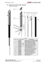
Page 19: ...34 Hoshizaki Lancer reserve the right to change specifications without notice Part No 68000028 Images are for illustration purposes only as product may vary No 061 2 17 December 2019 9 2 Bullet Tower...

Page 20: ...m Page 20 of 34 Hoshizaki Lancer reserve the right to change specifications without notice Part No 68000028 Images are for illustration purposes only as product may vary No 061 2 17 December 2019 9 3...

Page 21: ...reserve the right to change specifications without notice Part No 68000028 Images are for illustration purposes only as product may vary No 061 2 17 December 2019 9 4 Bullet Tower Customer Standard As...

Page 22: ...com Page 22 of 34 Hoshizaki Lancer reserve the right to change specifications without notice Part No 68000028 Images are for illustration purposes only as product may vary No 061 2 17 December 2019 9...

Page 23: ...ge 23 of 34 Hoshizaki Lancer reserve the right to change specifications without notice Part No 68000028 Images are for illustration purposes only as product may vary No 061 2 17 December 2019 9 6 Bull...

Page 24: ...erbeverage com Page 24 of 34 Hoshizaki Lancer reserve the right to change specifications without notice Part No 68000028 Images are for illustration purposes only as product may vary No 061 2 17 Decem...

Page 25: ...everage com Page 25 of 34 Hoshizaki Lancer reserve the right to change specifications without notice Part No 68000028 Images are for illustration purposes only as product may vary No 061 2 17 December...

Page 26: ...everage com Page 26 of 34 Hoshizaki Lancer reserve the right to change specifications without notice Part No 68000028 Images are for illustration purposes only as product may vary No 061 2 17 December...

Page 27: ...rage com Page 27 of 34 Hoshizaki Lancer reserve the right to change specifications without notice Part No 68000028 Images are for illustration purposes only as product may vary No 061 2 17 December 20...

Page 28: ...erage com Page 28 of 34 Hoshizaki Lancer reserve the right to change specifications without notice Part No 68000028 Images are for illustration purposes only as product may vary No 061 2 17 December 2...

Page 29: ...ge com Page 29 of 34 Hoshizaki Lancer reserve the right to change specifications without notice Part No 68000028 Images are for illustration purposes only as product may vary No 061 2 17 December 2019...

Page 30: ...ge com Page 30 of 34 Hoshizaki Lancer reserve the right to change specifications without notice Part No 68000028 Images are for illustration purposes only as product may vary No 061 2 17 December 2019...

Page 31: ...1000206 SCR 6 19X 910 PHD PH SL PLT 17 05 1593 02 21051593 DIFFUSER VERSAPOUR 3 0OZ 18 05 3242 21000207 NOZZLE BLACK VERSAPOUR 19 54 0183 04 21000208 NOZZLE ASSY 2 SHOT 4 5OZ S 20 04 0310 21000209 SCR...

Page 32: ...toff fully C Remove water soda flow control from upper body and clean out any foreign material to ensure smooth free spool movement Insufficient syrup flow A Insufficient CO2 pressure to BIB pumps B S...

Page 33: ...restriction C Valve flow control stuck A Check incoming syrup to ensure minimum flowing pressure B Check shutoff on mounting block to ensure it is in fully open position C Remove water flow control fr...

Page 34: ...al of the Divisional Sales Manager Lancer may choose to reimburse the customer for some or all labour costs associated with a warranty claim Any claim for labour costs must be authorized by Lancer pri...

Reviews: