background image

30

ADX-2400D Specifications 

Local Input Channels

24 AES on 12 unbalanced (BNC female) connectors, 1v p-p

Local Output Channels

24 AES on 12 unbalanced (BNC female) connectors, 1v p-p

AES Reference Input

AES Silence or other AES signal.  BNC connector, 75-ohm, 1v p-p

Output Phase Lock Ac/- 1% of sample period  (+/- 200 ns)

Input Phase Requirements

None.   Inputs may be free-running

Sample Rate Converters

Highest-quality AD1895.  Converters on both inputs and outputs.

Output Impedance

75 Ohms, transformer coupled

Input Impedance

75 Ohms AC termination, transformer coupled

Digital Processing and Delay 24-bit uncompressed

Cobranet Transmission

20-bit uncompressed

Sample Frequency

48 kHz

Adjustable Delay Range 

0 milliseconds to 680 milliseconds (>20 frames at 30 fps)

Minimum Delay (AES in to 
AES out)

1.5 milliseconds 

Minimum Delay (through 
Ethernet)

6.5 milliseconds in standard mode, 2.5ms in low-latency mode

Headphone Jack

1/4" TRS (Stereo) follows Output selection, Low impedance

Menu

Selects Cobranet bundle numbers (address), config store/recall 

Remote Control

GPI and RS-232 for special applications.  Contact Lance Design

VU Meter

Conventional VU ballistics (300ms), -20 to +3.5 dB scale, follows 
Output selection.  Scale mark at 0 VU.

Display

2x24 VFD

Power Requirements

95 to 250 Volts AC, 50-60 Hz, 15 Watts

Summary of Contents for ADX-2400D

Page 1: ...IBUTION AND DELAY SYSTEM AES Digital I O Installation and Operation Manual Software Version 5 1 October 2014 Lance Design 27 Fairview Avenue Ridgefield Connecticut 06877 Tel 203 894 8206 Fax 203 894 8207 www lancedesign com ...

Page 2: ...ill be made free of charge provided that the equipment has not been subjected to mechanical or electrical abuse or modification as determined by Lance Design and also that the equipment is returned to Lance Design with prior authorization No liability whatsoever is assumed for consequential damages resulting from the use or failure of this equipment This warranty is in lieu of all other warranties...

Page 3: ...age 10 Designing the Network Important Information Page 12 Installation Page 15 Specifications Page 16 Front Panel View Rear Panel View Please note that in all following descriptions the Physical Input and Physical Output channel designations refer to audio channels NOT to the BNC connector numbers on the rear panel Channels 1 and 2 are on BNC connector 1 Channels 3 and 4 are on BNC connector 2 et...

Page 4: ...is selected when the ADX 2400 is used to provide the head end or truck end of an ethernet based announce booth system using either ADX 120 Announce Units or ADX 140 XLR Interface Frames or both to provide a fully self contained announce booth system using copper or fiber ethernet as the transmission medium In this mode the ADX 2400 can support up to four ADX 120s or ADX 140s in any combination The...

Page 5: ...the ADX 2400D be equipped with a revision J or later Cobranet interface module If an earlier version module is installed and fault message will be displayed and low latency operation is not possible Also note that low latency operation puts more demands on the network performance Ethernet switches which operate comfortably with standard latency operation my not be satisfactory with low latency ope...

Page 6: ...RCE button It will light and the currently selected source for the selected output will be displayed The sources available for each output are as follows and can be selected by turning the knob SILENCE The output will be muted LOCAL INPUT The output will be fed by the corresponding local AES input NET INPUT The output will be fed by the corresponding network receiver 888HZ TONE The output will be ...

Page 7: ...the knob to select the desired menu item then press the MENU SET button Turning the knob will now change the parameter for this item When the desired selection is made you can exit the MENU SET mode by pressing any other button See section on menu items below MENU ITEMS NORMAL MODE Item 01 RX 1 8 Bundle 000 999 Packet assignment for network receiver 1 which corresponds to audio channels net inputs...

Page 8: ...f set to high this unit will be the conductor unless another is also set high In the case where more than one unit has equal priority the first unit active will assume the conductor role This selection isn t too important since the network will quickly re negotiate a new conductor if the current conductor were to fail or be turned off Item 08 Delay Units Milliseconds Frames 30 Frames 25 This item ...

Page 9: ... pressing MENU SET will cause the settings previously saved in the selected User Config file to be recalled Item 15 Recall Standard Config Pressing the MENU SET button will recall a standard configuration All levels will be set to unity all delays will be set to zero all local outputs will have their sources set to NET and all network outputs will have their sources set to LOCAL All bundle numbers...

Page 10: ...nsmitter is putting data on the network If assigned as a broadcast bundle 001 255 the status could be 0 Rcvrs if no receivers were listening to this bundle number The data is still present on the network Net TX 1 corresponds to net outputs 1 8 Status Item 05 NET TX 2 Status Idle or Number of Receivers Same as above for net outputs 9 16 Status Item 06 NET TX 3 Status Idle or Number of Receivers Sam...

Page 11: ...nel These two digits are used as the last octet of the network IP address 192 168 100 xx and the last part of the Cobranet system name Lance ADX2400D xx This IP address and system name appear when using the Cobranet Discovery application to report network node status Status Item 10 Firmware Version Displays the version and date of the installed firmware ...

Page 12: ...ach output is independent although you can select groups or all to save setup time if you are setting them all to be the same The unit should also be thought of as having 48 inputs 24 AES inputs on the back panel and 24 inputs from the network receivers Application Examples For stand alone delay all outputs would be set to local input and level and delay adjusted as desired The network tx rx would...

Page 13: ...led by selecting menu item 15 and pressing MENU SET It may also be recalled on power up or reset by turning on options dipswitch section 1 The factory default sets all levels to unity all delays to zero local output sources to net inputs and net outputs to local inputs All bundle numbers are set to zero Dipswitch functions Ver 5 1 firmware There is an Options Dipswitch located behind the front pan...

Page 14: ...RCE button as above Any physical input may feed more than one IFB The PGM Non Interrupt feeds going out on the network to the remote units may be fed from any of the 8 physical PGM inputs The selections are made using the SOURCE button as above Any physical input may feed more than one PGM Any of the PL channels at the remote devices may be assigned to any of the 4 wire ports on the back panel of ...

Page 15: ...r as Unit A in the ADX 2400 The mic outputs of the selected device will appear as Mic A1 and A2 the IFBs will appear as IFB A1 and IFB A2 etc The number selected corresponds to the System ID set on the rotary switches of the remote device 01 through 99 are valid IDs 00 is off and selects no remote device for Unit A Item 02 ANNOUNCE UNIT B ID 00 99 Item 03 ANNOUNCE UNIT C ID 00 99 Item 04 ANNOUNCE ...

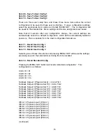
Page 16: ...e three items and pressing MENU SET will cause the settings previously saved in the selected User Config file to be recalled Item 14 Recall Standard Config Pressing the MENU SET button will recall a standard configuration This configuration is as follows Unit A ID 01 Unit B ID 02 Unit C ID 03 Unit D ID 04 Talkback Output 1 Physical Out 9 Unit A TB 1 Talkback Output 2 Physical Out 10 Unit A TB 2 Ta...

Page 17: ... items and are only to display status information They may not be directly changed by the user Status Item 01 Unit A RX Status Active or Idle Displays ACTIVE status if data is being received by network receiver 1 This receiver is used for audio signals coming from the remote device assigned as Unit A Status Item 02 Unit B RX Status Active or Idle Same for receiver 2 audio signals coming from the U...

Page 18: ...A high temperature indication might indicate a fan failure and will cause a fault message to be displayed if the temperature exceeds 55 degrees C Status Item 07 System ID 00 99 Displays two digit system ID for this ADX 2400 as set by rotary switches on the sub panel Status Item 08 Firmware Version Displays the version and date of the installed firmware ...

Page 19: ...h the rear panel outputs and the outputs sent to the network and thus to the remote devices The DELAY function is not available in announce booth mode 3 The Remote Device menus Each remote device ADX 120 140 has an internal menu which may be accessed remotely via the ADX 2400 These menus configure the hardware of the remote device itself and are specific to the particular model i e the ADX 120 has...

Page 20: ... panel The range for the switches is from 01 through 99 00 is not a valid ID No two devices may have the same ID number Compatibility ADX 2400Ds with version 5 1 or later firmware may be used with earlier ADX 120s or ADX 140s by turning on Dipswitch section 5 on the 2400 and using IDs for all devices with the first tens digit 0 This is provided as an emergency or interim operating mode All devices...

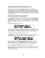
Page 21: ...will look similar to this The number in the brackets is the System ID assigned in the ADX 2400 for Unit A in this example If the selected device is present on the network it s model number and System ID number will be displayed ADX120 01 in this example Scroll to the desired assigned device either A B C or D Press MENU again This will access the menu of the remote device and the menu might look li...

Page 22: ...nsing Most networks are established by using standard Ethernet switch es The switches must support Layer 2 traffic Each ADX unit must be connected to the switch on its own port If multiple switches are used it is desirable for the switches to connect to each other using gigabit Ethernet A gigabit Ethernet link allows 700 or more audio channels to be sent in each direction A 100base T full duplex l...

Page 23: ...assignment in the range 256 999 is a Unicast Bundle These numbers are used for normal transmission from one transmitter to one receiver point to point A switch will route this traffic only to the required port and reduce unnecessary traffic on the network The audio transmission will usually follow the bundle assignment almost instantly however on occasion there will be a delay of a second or two a...

Page 24: ...es can not exceed 10 9 is better This number does not include bundles being transmitted by this frame The broadcast bundles are a very powerful feature in that they allow very convenient and inexpensive distribution of lots of audio signals Using broadcast bundles can really clog up the network however so be aware of the tradeoffs and use them only when required If the network traffic becomes too ...

Page 25: ...is available on their website www cobranet info or at www lancedesign com The PC TCP IP network properties must be set for a fixed IP address not DHCP and a subnet mask The firmware in the ADX 2400s sets their IP addresses to 192 168 100 xx where xx is the System ID set by the rotary switches on the PCB behind the front panel I recommend setting the PC IP Address to 192 168 100 200 although any nu...

Page 26: ...put is not designed to accept 48 Khz word clock The 12 outputs will be frequency and phased locked to this reference regardless of input or network timing There are no restrictions on the timing or locking of any of the 12 input signals They will be syncronized in the unit to the network clock All AES audio into the ADX 2400D should have emphasis turned off as emphasis is not supported internally ...

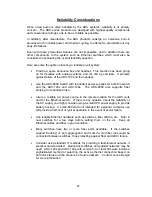
Page 27: ... also supports fiber trunking for redundant links Insure a reliable AC power source in the remote location for the ADX units and for the Ethernet switch If there is any question about the reliability of the AC supply you might consider using a small UPS power supply to provide battery backup A small 500 watt unit intended for personal computer use will provide a half hour of typical operation in t...

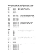
Page 28: ...e assigned to any of the 4 wire Out 19 4 Wire PL Port 3 Out ports Out 20 4 Wire PL Port 4 Out Out 21 4 Wire PL Port 5 Out Out 22 4 Wire PL Port 6 Out Out 23 4 Wire PL Port 7 Out Out 24 4 Wire PL Port 8 Out Inputs Input 1 IFB In 1 Each IFB output at the ADX120 140s may be fed Input 2 IFB In 2 from any if the eight physical IFB inputs Input 3 IFB In 3 Input 4 IFB In 4 Input 5 IFB In 5 Input 6 IFB In...

Page 29: ...ible pulled up to 5 volts with a 5K resistor They should be pulled to ground with a dry switch closure or O C transistor to activate GPIs used as outputs are open collector transistors with a 5K pull up resistor to 5 volts These transistors pull to ground when the GPI is active Current should not exceed 200 Ma When ADX 2400 is in Master GPI mode GPIs 1 and 2 are outputs and GPIs 3 and 4 are inputs...

Page 30: ...ansformer coupled Digital Processing and Delay 24 bit uncompressed Cobranet Transmission 20 bit uncompressed Sample Frequency 48 kHz Adjustable Delay Range 0 milliseconds to 680 milliseconds 20 frames at 30 fps Minimum Delay AES in to AES out 1 5 milliseconds Minimum Delay through Ethernet 6 5 milliseconds in standard mode 2 5ms in low latency mode Headphone Jack 1 4 TRS Stereo follows Output sele...

Reviews: