background image

PAGE 3

PLACING UNIT INTO SERVICE: 

1. 

Manually index the softener control into the backwash position. Slowly open bypass valve and allow water to flow into 

the resin tank. When the water flows steadily to drain without the presence of air, index control to service position. 
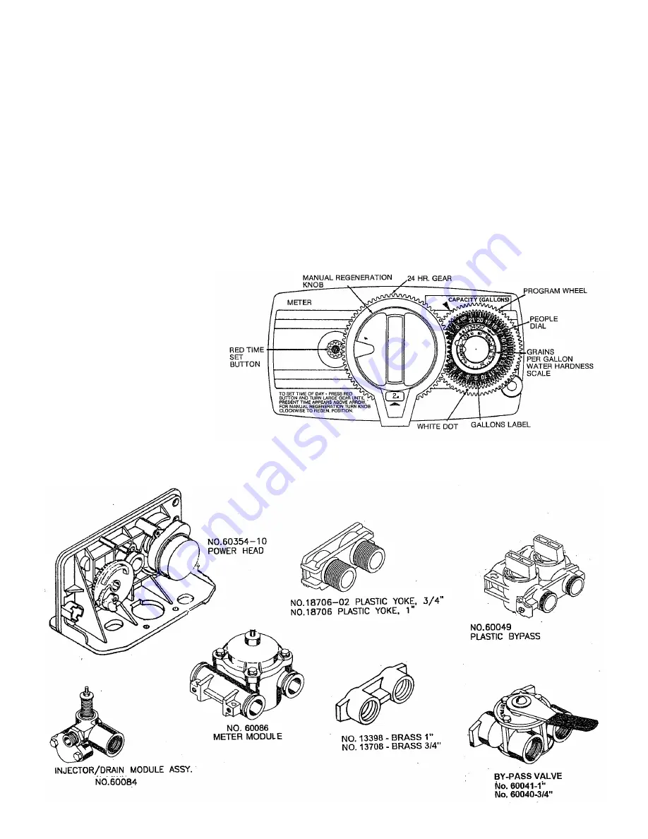
NOTE: the various regeneration positions may be dialed manually by turning the knob on the front of the control 

clockwise until the indicator shows that the softener is in the desired position. VARIOUS REGENERATION 

POSITIONS ARE: 


1. IN SERV. 

 3. RINSE 


5. BRINE + RINSE      7. SETTLE RINSE


2. REGEN. 

  4. BACK WASH 

6. RAPID RINSE    

8. BRINE REFILL

2. 

Set water usage program wheel using the following procedure:
Typical Residential Application: To program the unit, set the correct time of day, set the hardness of your water and 

the  softener will automatically monitor your usage, regenerating only when necessary. To set time of day press red 

time set button and turn 24 hour gear until present time of day is opposite “time of day.” Set program wheel by lifting 

the “people” dial and rotating it so that the number of people in the household is aligned with the “grains per gallon” 

water hardness scale. Release the dial and check for firm engagement at setting. (This method will provide reserve 

capacity based on 50 gallons per person.)

3.  Rotate the program wheel 

counter clockwise until it stops 

at regeneration position.

4.  Add 1-1/2 gallons of water to the 

brine tank.

5.  Plug in the electrical cord and 

look in the sight hole in the back 

of the motor to see that it is 

running.

6.  Manually advance the control to 

the beginning of the brine refill 

position and allow the control to 

return to the service  

position automatically.

7.  Fill the brine tank with salt. Maintain salt level above water level. We recommend Solar Salt.
8. 

Make sure bypass valve(s) is in the service position.

Summary of Contents for 7-LMC56-75B

Page 1: ...er please first contact the professional contractor who installed the system Congratulations on purchasing your new Lancaster Water Filter This unit is designed to give you many years of trouble free service For servicing and future inspection purposes please file this booklet with your important documents 7 LMC56 75B 7 LM56 75B 7 LM56 100B 7 LM56 150B 7 LM56 200B ...

Page 2: ...must be installed in a sewer line Place the trap as close to the vent as possible to prevent siphoning of the trap when large amounts of waste water go through the sewer line DO NOT pipe the drain line solidly into the waste line as this is prohibited by most plumbing codes The drain line should enter the trap from above so the water will not back up in the drain line if sewer should become plugge...

Page 3: ... monitor your usage regenerating only when necessary To set time of day press red time set button and turn 24 hour gear until present time of day is opposite time of day Set program wheel by lifting the people dial and rotating it so that the number of people in the household is aligned with the grains per gallon water hardness scale Release the dial and check for firm engagement at setting This m...

Page 4: ...ram Wheel Retainer 8 1 13175 Motor Mounting Plate 30 1 13748 Screw Program Wheel 9 1 18743 Motor 110 V 1 30 RPM 31 1 13953 Cover Label Program Wheel 10 3 11384 Screw 32 1 13830 Drive Pinion Program Wheel 11 3 13296 Screw 33 1 13831 Clutch Drive Pinion 12 2 14457 Spring 34 1 14276 Spring 13 2 13300 Ball 35 1 14253 Spring Retainer 14 1 13170 Main Gear Shaft 36 1 14043 Flexible Cable Assy 15 1 60514 ...

Page 5: ...ap 48 3 12112 Screws 9 1 10696 Piston Pin 30 1 13167 Brine Valve Spacer 49 1 13363 Washer 10 1 13001 Piston Rod Assy 31 1 12550 Quad Ring 50 1 13296 Screw 11 1 12953 Piston Retainer 32 1 11973 Spring 51 1 13398 Yoke Stainless Steel 12 1 13446 End Plug Assy 33 1 16098 Washer 52 1 13308 Drain Line Fitting 13 1 13847 O Ring 34 1 11981 Retaining Ring 53 1 14038 Meter Cover Assy 14 2 13315 Screw 35 1 1...

Page 6: ... Bypass Seal 3 1 11972 Bypass Plug 4 1 11978 Side Cover 5 1 13604 Valve Label 6 8 15727 10 24 x 1 2 machine Screw 7 1 11986 Side Cover 8 1 11979 Valve Lever 9 1 11989 1 4 14 x 1 2 Machine Screw Item No Qty Part No Description 1 1 19723 Bypass Valve Body Plastic 2 1 11183 O Ring 3 1 19724 Cap Bypass 4 2 17512 6 24x3 Screw 5a 1 17820 Plug Bypass Inlet White 5b 1 17820 01 Plug Bypass Outlet White 6 4...

Page 7: ...ly to assure proper function Make sure the control valve is returned to the service position Be sure grommet at cable hole is in place Make sure there is enough brine in the brine tank Rotate program wheel counter clockwise until it stops at regeneration position Start regeneration cycle manually if water is hard Plug cable into meter cover Rotate cable to align drive flat if necessary TO REPLACE ...

Page 8: ...s too much salt a Improper salt setting a Check salt usage and salt setting b Excessive water in brine tank b See problem no 7 4 Loss of water pressure a Iron buildup in line to water conditioner a Clean line to water conditioner b Iron buildup in water conditioner b Clean control increase frequency of regeneration and use a resin cleaner c Inlet of control plugged by foreign material c Remove pis...

Reviews: