Lampert PUK U4 Operating Manual Download Page 16


© Lampert Werktechnik GmbH


2015


15 

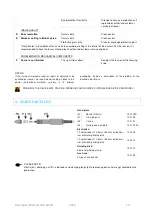
7.4 ABRADING THE ELECTRODES


Please switch off the machine prior to exchanging 
the  electrodes.  This  prevents  uncontrolled 

triggering of the welding process.   

If  possible,  the  electrodes  should  be  sharpened  with  a 
diamond disk with fine or medium grain.  

The recommended angle of grinding is approx. 15°.  


8. CARE OF THE SYSTEM COMPONENTS 


8.1


CARE OF WELDING DEVICE AND WELDING MICROSCOPE 

Your PUK U4 as well as the welding microscope require a 
minimum 

of 

maintenance 

under 

normal 

working 

conditions

.  However,  it  is  essential  that  a  few  points  are 

observed  in  order  to  guarantee  the  functionality  and  to 
keep the spot welding device fully operational for years to 
come. 

  Check the mains plug and cable as well as all welding 

and connection cables regularly for damage. 

  Check that the moving parts of the handpiece move 

easily. 

  If necessary, clean the electrode threaded assembly on 

the handpiece, in order to ensure optimal contact with 
the electrodes. 

  Clean the device occasionally with a suitable cloth. 

  Use the supplied dust cover to cover up the microscope 

after use.


IF WORK OR REPAIRS THAT ARE NOT DESCRIBED IN THESE OPERATING INSTRUCTIONS ARE NECESSARY 
THEN CONTACT YOUR DEALER. 


WARNING! 

IF FUSES REQUIRE EXCHANGING, THEN THEY MUST BE REPLACED WITH FUSES OF THE SAME TYPES 

AND VALUES.

THE GUARANTEE IS VOID IN THE EVENT OF EXCESSIVLY HIGH FUSING! 

THE DEVICE MAY ONLY BE OPENED BY AUTHORISED CUSTOMER SERVICE PERSONNEL! 


8.2


CARE OF THE OPTICAL COMPONENTS 

Do  not  attempt  to  disassemble  optical  components. 
Please  contact  the  local  technical  customer  service 
department  for  repairs  which  are  not  covered  by  this 
manual.  

Remove  dust  from  the  lens  surface  with  a  special  brush 
prior  to  cleaning.  You  can  obtain  suitable  accessories  in 
any photography store. 

Cleaning the oculars: Do not remove the oculars (19) from 
the ocular tubes (17). 

Clean  the  outer  surfaces.  In  doing  so,  blow  on  them. 
Subsequently dry the lens with suitable cloth or paper for 
the  purpose.  Dry  the  lens  with  circular  movements  from 

the centre to the outside. Do not wipe over a dried lens as 
they can easily be scratched.  

Cleaning  and  exchanging  the  protective  glass  of  the  eye 
protection filter: 

Never  dismantle  the  eye  protection  filter 
(shutter)! 

Only  clean  the  surface.  Use  a  cotton  cloth  with  glass 
cleaner.  

If  the  protective  glass  requires  exchanging,  slide  it 
forwards  out  of  the  bracket  and  insert  a  new  protective 
glass in the same manner. 


Summary of Contents for PUK U4

Page 1: ...Operating Manual PUK U4...

Page 2: ...OPERATION THE GENERAL SAFETY REQUIREMENTS AND PERSONAL BODY PROTECTION CHAPTERS MUST BE READ BEFORE COMMISSIONING Please keep these operating instructions safe The equipment produced by Lampert Werkt...

Page 3: ...election of the TIG welding parameters Pg 11 6 2 Help function Pg 12 6 3 Programming Pg 12 6 4 Loading saved WIG welding programs Pg 13 6 5 Resistance welding mode Pg 13 7 WELDING INSTRUCTIONS 7 1 Int...

Page 4: ...the mains and welding currents can be a source of danger Always remove the mains plug when exchanging the LED unit Only use original replacement LED units from Lampert The device must be isolated from...

Page 5: ...in protection class 10 In addition to light and thermal radiation which can cause dazzling and burning the electric arc also emits UV radiation With insufficient protection this invisible ultraviolet...

Page 6: ...ET FOR LED MICROSCOPE ILLUMINATION 6 TYPE PLATE 7 SERIAL NUMBER 8 PROTECTIVE GAS CONNECTION ARGON GAS for 6 0 mm diameter pressure hose 9 APPROVED MAINS VOLTAGE FOR THIS DEVICE 10 USB SOCKET FOR SERVI...

Page 7: ...up hand tight do not use a tool to tighten The correct length for the electrode can easily be checked and corrected if necessary by means of the milled marks on the handpiece clamping arm Fig 4 Now re...

Page 8: ...interocular distance should be individually set for each user FOCUSING Mount a welding handpiece with clamped electrode into the supporting arm Rotate the focusing knob 22 to a medium focus range Adj...

Page 9: ...as resistance welding devices 29 CONNECTION SOCKET FOR HAND PIECE 30 SOCKET 6 mm socket for connecting the blue contact terminal for resistance welding as well as resistance welding devices TOUCHSCREE...

Page 10: ...d custom settings c Resistance welding mode d Settings In user level TIG welding it is possible to use the arrow keys to scroll back and forth between the various pages e g between the preconfigured p...

Page 11: ...GS The Settings user level can be used to modify basic settings and launch various test functions Gas Test Pressing the corresponding button causes the gas valve to be opened This function is importan...

Page 12: ...welding time Welding times of no more than 4ms are recommended here With many alloys and other highly conductive metals a longer welding time can be advantageous in order to avoid hot cracks starting...

Page 13: ...e Use identical alloy wire with a diameter of 0 3 to 0 4 mm Particularly low energy fusing of thin welding wires of a max 0 25 mm PUSHING TOUCHING THE RESPECTIVE BUTTON FOR AN EXTENDED PERIOD BRINGS U...

Page 14: ...FUNCTION OF THE EYE PROTECTION FILTER AS DESCRIBED IN CHAPTER 5 5 FILTER TEST IF THE EYE PROTECTION FILTER SHUTTER FAILS TO SWITCH OVER FROM LIGHT TO DARK THEN IT MUST BE IMMEDIATELY EXCHANGED BY AUT...

Page 15: ...e black When the two parts are touching the welding process can be triggered using the foot switch The hand piece is not used during this process The required welding power is determined by the streng...

Page 16: ...HAT ARE NOT DESCRIBED IN THESE OPERATING INSTRUCTIONS ARE NECESSARY THEN CONTACT YOUR DEALER WARNING IF FUSES REQUIRE EXCHANGING THEN THEY MUST BE REPLACED WITH FUSES OF THE SAME TYPES AND VALUES THE...

Page 17: ...ly in dry rooms Operating temperature Lamp LED unit Protection class Insulation class Protection type Weight 5 C to 40 C 2 5W 800mA III B IP 20 3 6 Kg 9 3 OPTICAL DATA MICROSCOPE Lens Ocular Working d...

Page 18: ...load Tungsten inert gas welding Earthing earth Nominal welding current Power consumption under max load Power consumption under nominal load Cyclic duration factor Single phase transformer Keep away f...

Page 19: ...firmly 7 Oxidation and rusting Excessive gas pressure Reduce flow rate approx 2 l min is recommended 8 Severe oxidation of the welding points Incorrect shielding gas Use inert shielding gas Argon 4 6...

Page 20: ...ocusing knob REPAIR If the stereo microscope requires repair or adjustment by qualified personnel we recommend sending it back to the dealer authorized customer service in its original packaging Inclu...

Page 21: ...e disposal of used electrical and electronic equipment discarded electrical devices must be separated and collected and sent for recovery in an environmentally friendly manner 13 EC DECLARATION OF CON...

Page 22: ...Born in Germany Lampert Werktechnik GmbH Ettlebener Stra e 27 D 97440 Werneck Tel 49 9722 9459 0 mail lampert info www lampert info Rev 4 0...

Reviews: