LAMETAL Stark THM 2500 Original Operating And Maintenance Instructions Download Page 18


Sivu 18 / 20 
 

9.


HYDRAULICS 

The back broom can be connected in two different ways, either with two (figure 1) or four (figure 2) hoses. When 
connecting with two hoses, the hydraulics of the basic machine is connected to quick connectors and a separate switch 
is used to choose whether the broom is rotated or turned. When connecting with four hoses, a rotation cylinder and the 
rolling of the engine are connected separately to the hydraulics of the basic machine. This means that the lifting and 
rotating of the broom can be done with the hydraulics of the basic machine, and no separate control valve is needed. 
 
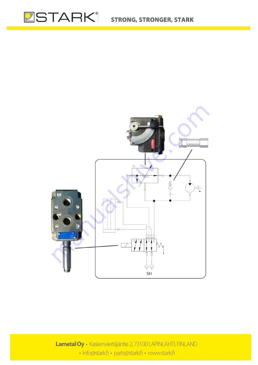
The rotation speed of the broom is adjusted with the valve shown on figure 1. The suitable position is usually found 
between 5 and 8. If there is a flow controller in the basic machine, the speed control valve can be set to position 10. 
 
SH = Cylinder hydraulics 

MH = Motor hydraulics 


Figure 1. 2-hose hydraulics  

Summary of Contents for Stark THM 2500

Page 1: ...Original Operating and maintenance manual Back broom 2500 3000...

Page 2: ...ebpage www stark fi for the complete product range including new products The manufacturer reserves the right for structural and technical changes without prior notice Therefore some pieces of informa...

Page 3: ...ck broom 9 7 2 Overload switch 10 7 3 Changing the brush rings 11 7 4 Adjusting the chains 12 7 5 Removing the back broom from the base machine 13 7 6 Transferring the back broom 13 8 MAINTENANCE OF T...

Page 4: ...ert j ntie 2 73100 LAPINLAHTI Finland tel 358 17 731 565 Declares that the above mentioned equipment meets the provisions of Directive 2006 42 EC on machinery and where applicable comply with the stan...

Page 5: ...s and objects that block your view children use of turn signal when driving NEVER use the machine if there is someone in the danger zone NEVER go under the attachment WARNING Rotating rollers During m...

Page 6: ...the serial number of your back broom Product and model _______________________________Serial number___________________________________ 4 2 Maintenance services When replacing parts use original manufa...

Page 7: ...CK BROOM Picture 2 Main parts of the back broom 1 Back broom s frame 2 Propeller shaft 3 Angle gear box 4 Front propeller shaft 5 Rotating triangle 6 Hydraulic cylinder 7 Broom roller 8 Chain 9 Brush...

Page 8: ...the base machine please pay attention to the instructions on the use of the base machine 1 Make sure that the attachment and the base machine are compatible in terms of mechanical solutions hydraulic...

Page 9: ...tors are clean and the hoses are intact 5 Lift back brooms front support legs Lock them in upward position with locking cotters 6 Check carefully the attachment s the base machine s and the fitting s...

Page 10: ...ed when the overload switch opens Slow down the driving speed or stop completely until the overload switch operates normally Overload switch is a safety mechanism which can be damaged when used incorr...

Page 11: ...ing new brush rings turn them 180 if needed so that the spikes of the rings are evenly placed and the rings don t have large gaps between them 7 Make sure that the spikes of the rings don t touch the...

Page 12: ...o tight they will strain cogwheels and axle s bearings Chains are behind their protective cases Adjusting the chains 1 Remove the protective case 2 Loosen 4 bolts in a bearing plate picture 10 3 Adjus...

Page 13: ...ugs 5 Unlock the coupling mechanism and detach the device 6 If the equipment is not likely to be used for a longer period of time clean it thoroughly after operating and lubricate as instructed Remove...

Page 14: ...148 M16 230 M18 329 M20 464 M22 634 M24 798 M27 1176 M30 1597 M33 2161 M36 2778 M39 3597 Table 1 Tightening torque 8 3 Daily maintenance In order to prevent further damages it is important to inspect...

Page 15: ...r the hydraulic cylinder 3 Grease nipples for the support wheels at both wheels 4 Grease nipples for the bearing at the top of the chain 5 Grease nipples for the propeller shaft s grating detailed ins...

Page 16: ...rizontal the oil level must be at least level with the minimum level shown on the dip stick You can access the plug of the box by detaching the protective sheet behind the box which is attached by fou...

Page 17: ...every 8 operating hours Add grease to the grating until it starts to pour out Picture 18 Propeller shaft s shape tubes need to be greased regularly after every 50 operating hours Vaseline spray is sui...

Page 18: ...linder and the rolling of the engine are connected separately to the hydraulics of the basic machine This means that the lifting and rotating of the broom can be done with the hydraulics of the basic...

Page 19: ...Sivu 19 20 Figure 2 4 hose hydraulics...

Page 20: ...s travel and waiting hours daily allowances travel expenses or costs arising from detaching and reinstalling the equipment The manufacturer does not compensate for indirect costs caused by repairs dur...

Reviews: