


4
(95666) TROPOS
Operating Instructions
Operating Instructions
Data logger TROPOS (95666)
4.2
Operation via push- / rotary switch
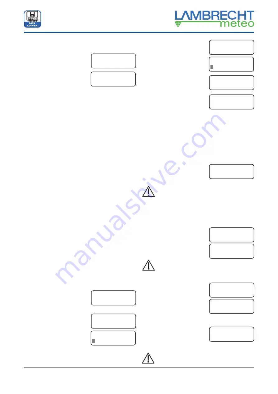
1. When TROPOS is connected to the supply voltage (after
finish of all wiring operations),
the system starts automatically.
This indication appears in the
display for a few seconds:
2. Afterwards the adjusted date
and time appear in the display.
3. The display turns off and TROPOS changes into the standby
mode after a while without operations at the push-/ rotary
switch. TROPOS is still working in the background.
4. The display turns on when the push-/ rotary switch is
pressed again. Date and time are shown.
5. The below mentioned menu items appear one after another
in the display when rotating the push-/ rotary switch (
menu
mode
):
turn right, clockwise = to go ahead;
turn left, anticlockwise = to go back.
6. Depending on the active menu item in the display a fur-
ther pressing of the push-/ rotary switch can be cause
the changing into the
edit mode
or the changing into a
submenu (see also chapter 4.3, the several menu items).
The edit mode
: The clockwise rotation of the push-/ rotary
switch by one step changes the value behind the blinking
rectangle (cursor function) about +1. The anticlockwise ro-
tation by one step changes this value about -1. By the next
pressing the switch the cursor goes ahead to the next digit.
By the rotation of the switch again the value of this digit is
changed in the same way. When the last digit is reached,
the
edit mode
can be fi nished by pressing the switch again.
The last adjusted values are saved.
4.3
The menu items
All menu items of menu appear by rotation of the push-/ rotary
switch within an infi nite loop:
· TROPOS,
Date,
Time
· Date
· Time
· Realtime
Values
· ID
Number
·
Change Battery
(Attention!)
· Change
CF
(Attention!)
· Display
Off
TROPOS, Date, Time
The indication of date and time
appear automatically in the LCD
of TROPOS.
Date
The date is adjustable in the
format DD.MM.YY.
After pressing the switch, it is
changing into the
edit mode
(see
above chapter 4.2, point 6).
By the next rotation of the switch the menu item
Date
ends
and the next menu item
Time
appears ... and so on.
Time
The time is adjustable in the
format hh:mm:ss, similarly to the
adjustment of the date.
Realtime Values
At this menu item pressing the
switch effects the changing into a
submenu.
Depending on the confi gured (in
„
TROPOS-Commander
“) and con-
nected (on TROPOS) sensors the
first measured value appears in
the display.
By rotation of the switch the list
of the realtime values of the con-
nected sensors is scrolled up or
down. By pressing the switch the
submenu is left.
ID Number
The station number can be shown
and changed like above mentioned.
The station number is used to identify the collected
values in the PC evaluation software. The default is
„0001“. This number should only, but always then
be changed, if more than one TROPOS system are
working in a RS 485 data bus system. The admis-
sible range is 1 to 9999.
Change Battery
A replacement of the battery is
only allowed, when this menu
item is activated and the indication
“Ready” appears in the display,
as submenu after pressing the
switch.
If this is ignored, data losses occur in rarely
cases.
Change CF-Card
The CF card may only be removed
when this menu item is activated
and
„Remove CF“
appears in the
display
,
as submenu after pressing
the switch. All writing procedures
have been fi nished.
To remove the CF card the button
left-hand beside the slot has to be pressed.
The indication „Insert CF“ gives the
order to insert a new CF card into
the slot. The values of the next 15
minutes can be saved at the RAM
before data losses occur (see also chapter 5.1).
Do not insert the card into the slot forcibly!
Do not cant!
TROPOS V 1.xx
System init...
TROPOS 23.03.16
20:58:00
TROPOS 23.03.16
20:58:00
Date
23.03.16
Edit Date
3.03.16
Time
20:58:00
Edit Time
0:58:00
Realtime Values
Press Key
Wind speed
0.5 m/s
Example:
realtime value of
wind speed
ID Number
0001
Change Battery
Press Key
Change Battery
Ready
Change CF
Remove CF...
Change CF
Press Key
Change CF
Insert CF...


