https://www.lairdconnect.com/
4
© Copyright 2022 Laird Connectivity
All Rights Reserved
Americas
: +1-800-492-2320
Europe
: +44-1628-858-940
Hong Kong
: +852 2762 4823
Note:
if you are working with CL4490-1000-232 or CL4490-1000-485
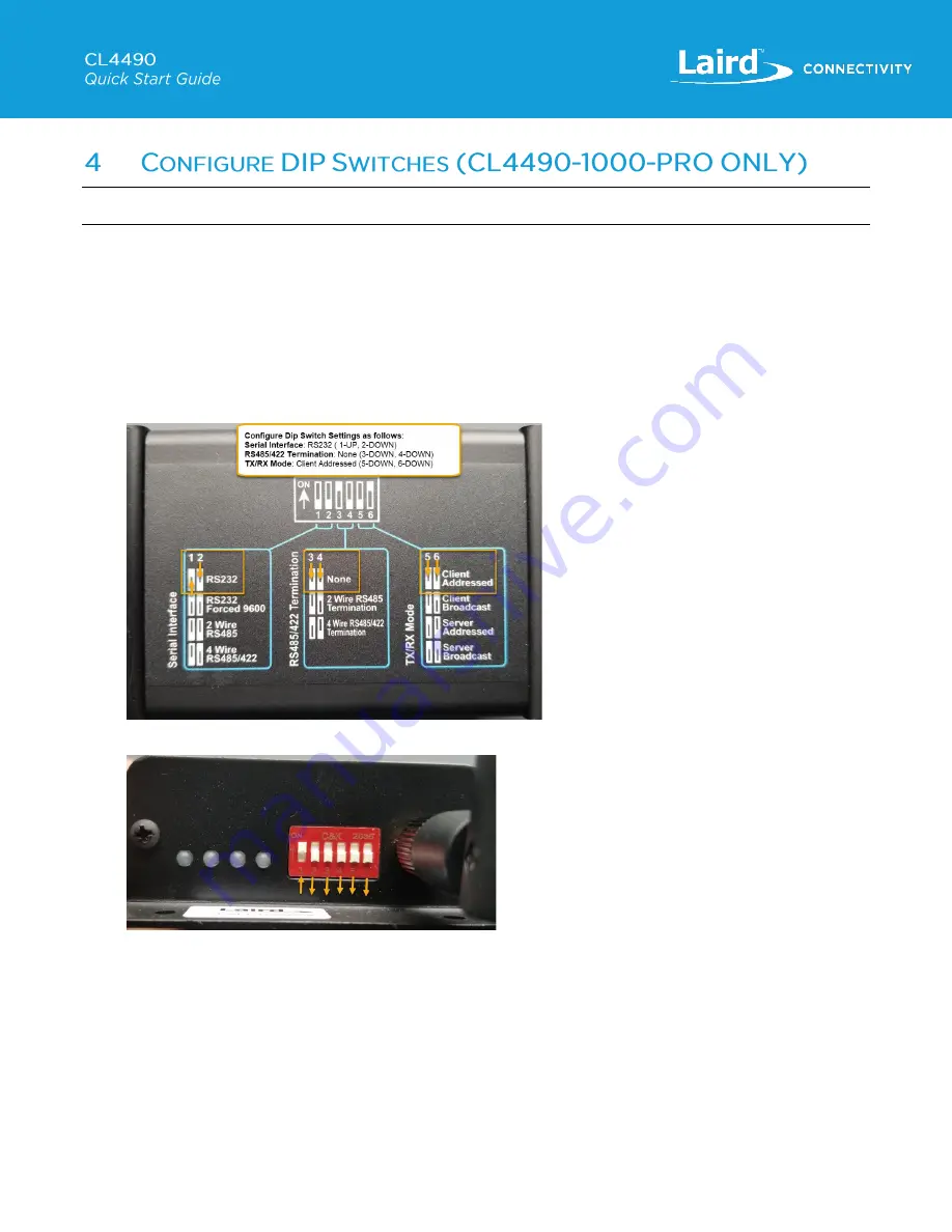
The CL4490-1000-PRO radios have DIP switches on the side of the radio, near the antenna and LEDs as shown below, which
enable you to select the
Serial Interface
,
Termination Settings
, and
TX/RX Mode
of the radio. These settings override any
EEPROM configurations, and so must be configured correctly to operate as expected with the settings that will be configured
on the radio with the Laird Configuration and Test Utility software.
In order to configure the radios so they can be connected via the RS232 Interface to a PC, to enable configuration with the
Laird Configuration and Test Utility software follow these steps:
1. On 1
st
radio configure the DIP switches, as per the diagram on the bottom of the CL4490-1000-Pro unit for Serial
Interface:
RS232
, Termination:
None
, TX/RX Mode:
Client Addressed
Figure 7: DIP Switch Config Diagram
– Client
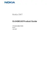
Figure 8: Client DIP Switch Settings


