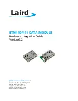
BTM410/411
Bluetooth
®
AT Data Module Hardware Integration Guide
Americas: +1-800-492-2320 Option 2
Europe: +44-1628-858-940
Hong Kong: +852-2923-0610
www.lairdtech.com/bluetooth
8
CONN-HIG-BTM410-411
Pin #
Signal
Description
Voltage Specification
40
Unused
41
GND
42
GPIO1 / UART_RI
I/O for host
VIO
43
GPIO7 / UART_ DTR
I/O for host
VIO
44
GPIO8 / UART_DSR
I/O for host
VIO
45
GND
46
D-
Not used for AT module variants
VUSB
47
D+
Not used for AT module variants
VUSB
48
GPIO6
I/O for host - RF_Active
VIO
49
GPIO5
I/O for host - WLAN_Active
VIO
50
GPIO3
I/O for host - BT_Priority
VIO
1.
Unused pins may have internal connections and must not be connected.
2.
Reset input is active low. Input is pulled up to VDD_IN via 22k. Minimum reset pulse width is 5 ms.
3.
Pins 8 – 11 (SPI related) are only for Laird internal production purposes.
4.
Pins 25-37 should be left not connected on modules with integrated antenna.
2.3
Operating Parameters
Table 2-3: Operating parameters
Operating Condition
Min
Max
VDD_USB (USB compatibility not required)
1.7
3.6
VDD_USB (USB compatibility required)
3.1
3.6
VDD_IO
1.7
3.3
VDD_IN
3.0
3.3
2.4
Voltage Specifications
Table 2-4: Voltage specifications (VUSB)
Min
Typ
Max
Input Voltage Levels
Vih
0.7VDD_USB
Vil 2.7<VDD_USB<3.0
1.7<VDD_USB<1.9
-0.4
-0.4
+0.8
-0.4
Output Voltage Levels (1.7<VDD_USB<1.9)
Voh (Iout = -4mA)
VDD_USB – 0.4
Vol (Iout = 4mA)
0.4
Output Voltage Levels (2.7<VDD_USB<3.0)
Voh (Iout = -4mA)
VDD_USB – 0.2
Vol (Iout = 4mA)
0.2
Note: VDD_USB must be connected to power the USB and UART interfaces.


