background image

www.lairdtech.com

H

ARDWARE

 I

NTERFACE

8

Below is a description of all hardware pins used to control the AC4868-250.

P I N   D E F I N I T I O N S

G e n e r i c   I / O

Both GIn pins serve as generic input pins and both GOn pins server as generic output pins. Reading and writing of
these pins can be performed using CC Commands.

T X D   &   R X D

S E R I A L   T T L

The AC4868-250 accepts 3.3VDC TTL level asynchronous serial data on the RXD pin and interprets that data as either
Command Data or Transmit Data. Data is sent from the transceiver, at 3.3V levels, to the OEM Host via the TXD pin.

R S - 4 8 5

When equipped with an onboard RS-485 interface chip, TXD and RXD become the half duplex RS-485 pins. The
transceiver interface will be in Receive Mode except when it has data to send to the OEM Host. TXD is the non-
inverted representation of the data (RS485A) and RXD is a mirror image of TXD (RS485B). The transceiver will still use
RTS (if enabled).

H o p   F r a m e

Transitions logic Low at the start of a hop and transitions logic High at the completion of a hop. The OEM Host is not
required to monitor Hop Frame. The AC4868 is a single frequency radio that uses fictitious hops, though it generates
a Hop Frame signal every time it transmits a timing beacon.

C T S

The AC4868-250 has an interface buffer size of 256 bytes. If the buffer fills up and more bytes are sent to the
transceiver before the buffer can be emptied, data loss will occur. The transceiver prevents this loss by asserting CTS
High as the buffer fills up and taking CTS Low as the buffer is emptied. CTS On and CTS Off control the operation of
CTS. CTS On specifies the amount of bytes that must be in the buffer for CTS to be disabled (logic High). Even while
CTS is disabled, the OEM Host can still send data to the transceiver, but it should do so carefully. 
Note: The CTS On/Off bytes of the EEPROM can be set to 1, in which case CTS will go high as data is sent in and low
when buffer is empty.

G N D

Signal Ground. Pins are internally connected.

R T S

With RTS disabled, the transceiver will send any received data to the OEM Host as soon as it is received. However,
some OEM Hosts are not able to accept data from the transceiver all of the time. With RTS enabled, the OEM Host can
prevent the transceiver from sending it data by disabling RTS (logic High). Once RTS is enabled (logic Low), the
transceiver can send packets to the OEM Host as they are received. 

Downloaded from 

Elcodis.com


electronic components distributor


Summary of Contents for AC4868-250

Page 1: ...VERSION 1 4 Downloaded from Elcodis com electronic components distributor ...
Page 2: ...ch as military medical life support or life sustaining equipment are specifically not recommended without additional testing for such application Limited Warranty Disclaimer Limitation of Liability For a period of one 1 year from the date of purchase by the OEM customer Laird Technologies warrants the OEM transceiver against defects in materials and workmanship Laird Technologies will not honor th...

Page 3: ...Downloaded from Elcodis com electronic components distributor ...

Page 4: ... interface section Corrected EEPROM write command response Version 1 3 9 18 07 Internal Release Version 1 4 9 5 08 Updated to Laird Technologies branding Clarified Duty Cycle calculations Updated information on client to client communications Corrected Read Temperature Command to a max of 0x50 Updated Minimum Baud Rate Downloaded from Elcodis com electronic components distributor ...

Page 5: ...ange Refresh 13 Auto Config Parameters 13 Max Power 14 Timing Diagrams 15 AC4868 250 Timing Diagrams 15 Hardware Interface 17 Pin Definitions 17 Configuring the AC4868 250 19 AT Commands 20 Command Descriptions 22 EEPROM Parameters 26 Dimensions 29 Mechanical Drawings 29 Ordering Information 30 Product Part Number Tree 30 Developer Kit Part Numbers 30 Compliancy Information 31 Agency Identificatio...

Page 6: ...ons include both system and configuration data The Host supplies system data for transmission to other Host s Configuration data is stored in the on board EEPROM All synchronization and RF system data transmission reception is performed by the transceiver AC4868 250 transceivers can operate in a Point to Point Point to Multipoint or Peer to Peer architecture The AC4868 250 utilizes a single channe...

Page 7: ...equency Band Europe 500 mW 869 4 869 65 MHz RF Data Rate 19 2 kbps or 28 8 kbps dependent on interface baud rate RF Technology Single Frequency FSK Output Power Conducted no antenna EIRP 2 5dBi gain antenna 186mW typical 250mW typical Supply Voltage Pin 10 uP power 3 3 5 5V 50mV ripple draws 30 50mA Must be connected Pin 11 PA power 3 3 3 100mV ripple draws most current Must be connected Sensitivi...

Page 8: ...it is not ready to accept data from the transceiver NOTE Keeping RTS High for too long can cause data loss 9 O GO1 Generic Output pin 10 PWR VCC1 3 3 5 5V 50mV ripple Powers the radio s uP Draws 30 50mA 11 PWR VCC2 3 3V 50mV ripple Powers the radio s power amplifier Current draw depends on duty cycle and output power 12 I Test Test Mode When pulled logic Low and then applying power or resetting th...

Page 9: ... V Command Data 2 31 3 3 0 0 99 V AD In N A 3 3 0 N A V Ta b l e 4 O u tp u t V o l ta g e C h ar a ct er i st i c s Signal Name Module Pin Type High Min Low Max Unit GO0 1 O 2 5 8mA 0 4 8mA V TXD 2 O 2 5 2mA 0 4 2mA V RS485A B 2 3 I O 3 3 1 8 Unit Load N A V CTS 7 O 2 5 2mA 0 4 2mA V GO1 9 O 2 5 2mA 0 4 2mA V DA_Out 19 O N A N A V1 1 DA_Out is an unbuffered high impedance output and must be buffe...

Page 10: ... S S E D P A C K E T S When sending an addressed packet the RF packet is sent only to the receiver specified in destination address To increase the odds of successful delivery Transmit retries are utilized transparent to the OEM Host the sending radio will send the RF packet to the intended receiver If the receiver receives the packet free of errors it will return an RF acknowledge within the same...

Page 11: ... en d i n g R F an d D a ta i n B u ff er F l ow Receive Mode Broadcast Packet Receive full packet and check CRC Addressed Packet Matching Destination MAC Validate CRC Duplicate Packet Send RF Acknowledge Send Packet over RF Duplicate Packet Discard Packet Discard Packet Send Packet over RF Pending RF Received Yes Yes Yes Yes Yes Yes Receive Mode Pin 17 Low Data in Buffer AT RF Data Broadcast Pack...

Page 12: ... the Broadcast Attempts For Addressed Packets data will be transmitted until a successful acknowledgement is received The OEM is responsible for limiting the Transmitter s on time to less than the duty cycle regulations T r a n s m i t C a l c u l a t i o n s For a rough estimate the TX Time on is 53ms the number of retries or attempts By default this is 212ms For servers you need to a 5ms beacon ...

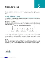
Page 13: ...fixed baud rate and by using START and STOP bits A typical asynchronous mode signal is shown below F i g u r e 2 A s y nc h ro n o u s Mo d e S i g n al The UART outputs and inputs logic level signals on the TX and RX pins The signal is high when no data is being transmitted and goes low when transmission begins The signal stays low for the duration of the START bit and is followed by the data bit...

Page 14: ...ormats are supported SERIAL INTE RFACE BAUD RATE This two byte value determines the baud rate used for communicating over the serial interface to a transceiver The Table below lists values for some common baud rates Baud rates below 1200 and above 57 600 baud are not T a bl e 6 S u p p or t ed S e r i a l F o r m a ts Data Bits Parity Stop Bits Transceiver Programming Requirements 8 N 1 Parity Dis...

Page 15: ...ds over the RF contains extra header bytes which are not included in the RF Packet Size However if the RF Packet Size is set too large the transceiver will not be able to send any packets because the AC4868 requires the entire RF packet to be sent in the same hop period 53 ms The RF packet size if programmed in EEPROM automatically when Auto Config is enabled It is strongly recommended that Auto C...

Page 16: ...CY Care should be taken when selecting transceiver architecture as it can have serious effects on data rates latency and overall system throughput The importance of these three characteristics will vary from system to system and E N G I N E E R S T I P Can I implement a design using just Txd Rxd and Gnd Three wire Interface Yes However it is strongly recommended that your hardware monitor the CTS ...

Page 17: ...tency will be introduced in the system when considering high density applications In these cases we can just offer qualitative analysis of the latency in high density applications As the network load increases then the number of collisions that will occur increases As the number of collisions increase then the system latency increases As the distance between the transceivers increases so to does t...

Page 18: ...xD6 It is highly recommended that this Key be changed from the default RANGE REFRE SH Range Refresh Range Refresh specifies the maximum amount of time a Client reports in range without having heard a beacon from the Server Each time the Client hears a beacon it resets its Range Refresh timer If the timer reaches zero the Client will go out of range take its In_Range pin High and enter acquisition ...

Page 19: ...ower setting Contact Laird Technologies for assistance in adjusting Max Power T a b l e 1 0 A u t o C o n f i g P a r a m e t e r s Parameter EEPROM Address Default RF Baud 19 200 RF Baud 28 800 Addressed Broadcast Addressed Broadcast RF Packet Size 0x5B 0x24 0x24 0x40 0x50 0x60 E N G I N E E R S T I P The max power is set during Production and may vary slightly from one transceiver to another The...

Page 20: ... DIAGRAMS Fi g ur e 4 A d dr e ss e d Mo d e w i th T i m eo u t Fi gu r e 5 A dd r e ss ed Mo d e w i th F i x e d P ac k et L e ng t h F i g ur e 6 B r oa d ca s t Mo d e w i th T i m e o u t Downloaded from Elcodis com electronic components distributor ...

Page 21: ...TI M I N G D I A G R A M S 16 F i g ur e 7 B r oa d ca s t M o d e w i th F i x ed P ac k et L en g th Downloaded from Elcodis com electronic components distributor ...

Page 22: ...that uses fictitious hops though it generates a Hop Frame signal every time it transmits a timing beacon C T S The AC4868 250 has an interface buffer size of 256 bytes If the buffer fills up and more bytes are sent to the transceiver before the buffer can be emptied data loss will occur The transceiver prevents this loss by asserting CTS High as the buffer fills up and taking CTS Low as the buffer...

Page 23: ...o other transceivers and their OEM Hosts When logic Low the transceiver interprets OEM Host data as command data A D I n D A O u t AD In DA Out can be used as a cost savings to replace Analog to Digital and Digital to Analog converter hardware Reading of this pin can be performed locally using the Read ADC command found in the On the Fly Control Command Reference DA Out is an unbuffered high imped...

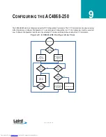
Page 24: ...Software Configuration can be used by entering AT Command Mode before issuing the CC Commands F i g u r e 8 A C 48 6 8 25 0 C o n fi g u r at i o n F l o w Use AT Commands Receive Mode Take Pin 17 Low Hardware Configuration AT Software Configuration Send CC Commands Exit Command Mode In AT Command Mode Send CC Command Send Another CC Command Send Exit AT Command Mode Command Take Pin 17 High No No...

Page 25: ...ommand mode and forward these to the OEM Host While in CC Command mode using AT Commands the RF interface of the transceiver is active but packets sent from other transceivers will not be received The transceiver uses Interface Timeout RF Packet Size to determine when a CC Command is complete Therefore there should be no delay between each character as it is sent from the OEM Host to the transceiv...

Page 26: ...5 Byte 6 0xCC Byte 4 of Dest MAC Byte 5 Byte 6 Read Destination Address 0xCC 0x11 0xCC Byte 4 of Dest MAC Byte 5 Byte 6 Auto Destination 0xCC 0x15 bit 0 Auto Destination bit 4 Enable Auto Destination 0xCC bit 0 Auto Destination bits 1 7 0 Read Digital Inputs 0xCC 0x20 0xCC bit 0 GI0 bit 1 GI1 Read ADC 0xCC 0x21 0x01 AD In 0x02 Temp 0xCC MSB of 10 bit ADC LSB of 10 bit ADC Write Digital Outputs 0xC...

Page 27: ...ent in Range 0x03 for Client out of Range Change Server Client The OEM Host issues this command to change the mode of the transceiver from Server to Client and vice versa Command 0xCC 0x03 Data1 Number of Bytes Returned 3 Response 0xCC Firmware Version Data1 Parameter Range Data1 0x00 for Server 0x03 for Client Sleep Walk Power Down After the Host issues this command the transceiver will de assert...

Page 28: ...r packet delivery Command 0xCC 0x11 Number of Bytes Returned 4 Response 0xCC MAC3 MAC2 MAC1 Parameter Range 0x00 0xFF corresponding to 3 LSB s of destination MAC Address Auto Destination The Host issues this command to change the Auto Destination setting When issuing this command the Auto Destination setting will only be changed if the corresponding enable bit is set Control1 Parameter EEPROM addr...

Page 29: ... 0xCC Data1 Data2 Parameter Range Data1 Update Period Data2 Duty cycle Set Max Power The OEM Host issues this command to limit the maximum transmit power emitted by the transceiver This can be useful to minimize current consumption and satisfy certain regulatory requirements The radios are shipped at maximum allowable power Command 0xCC 0x25 Max Power Number of Bytes Returned 2 Response 0xCC Max P...

Page 30: ...til the EEPROM write cycle is complete up to 10 ms Multiple byte writes of up to 128 bytes are allowed An EEPROM boundary exists between addresses 0x7F and 0x80 No single EEPROM write command shall write to addresses on both sides of that EEPROM boundary Command 0xCC 0xC1 Data1 Data2 Number of Bytes Returned 4 Response Data1 Data2 Data Parameter Range Data1 EEPROM address Data2 Length 0x00 0x80 Da...

Page 31: ...of time a transceiver will report In Range without having heard a Server s beacon equal to hop period value Do not set to 0x00 Stop Bit Delay 0x3F 1 0x00 0xFF 0xFF For systems employing the RS 485 interface or Parity the serial stop bit might come too early Stop bit delay controls the width of the last bit before the stop bit occurs 0xFF Disable Stop Bit Delay 12 us 0x00 256 1 6 us 12 us 0x01 0xFE...

Page 32: ...the Interface Baud Rate and RF Delivery mode Must be set to a minimum of 6 in order to send the Enter AT command CTS On 0x5C 1 0x01 0xFF 0xC0 CTS will be deasserted High when the transmit buffer contains at least this many characters CTS Off 0x5D 1 0x00 0xFE 0xB0 Once CTS has been deasserted CTS will be reasserted Low when the transmit buffer is contains this many or less characters Max Power 0x63...

Page 33: ...ut should not be modified Product ID 0x90 15 0x90 0x93 Product ID 0x94 0x95 Prefix AC 0x96 0x99 Power 250M 0x9A 0x9C Interface 485 TTL 0x9D 0x9E Setup script 01 is stock 0x9F Reserved for future use always 0xFF DES Key 0xD0 7 0x00 0xFF 56 bit Data Encryption key T a b l e 1 2 E E P R O M P a r a m e t e r s Parameter EEPROM Address Length Bytes Range Default Description Downloaded from Elcodis com...

Page 34: ...86 8 2 50 w i t h M M C X c o nn e ct o r M e ch a ni ca l 0 000 0 100 0 150 0 435 1 900 1 875 0 825 0 125 dia non plated holes 2 places 0 000 0 100 1 010 1 650 1 550 pins 1 2 1 650 0 000 0 067 0 000 0 157 0 062 0 180 M M C X jack J1 20 pin header 0 020 sq posts on 0 079 inch 2m m centers 1 320 1 760 0 100 dia non plated hole 1 place under shield M M C X jack 0 145 dia Downloaded from Elcodis com ...

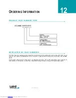
Page 35: ...with SDK As an example part number AC4868 250M can be ordered as a development kit using the part number SDK AC4868 250M All developer s kits include 2 transceivers 2 development boards 2 7 5 VDC unregulated power supplies 2 serial cables 2 USB cables 2 antennas configuration testing software and integration engineering support Downloaded from Elcodis com electronic components distributor ...

Page 36: ...reduced or enlarged the proportions given in the following graduated drawing must be respected 2 The CE marking must have a height of at least 5 mm except where this is not possible on account of the nature of the apparatus 3 The CE marking must be affixed to the product or to its data plate Additionally it must be affixed to the packaging if any and to the accompanying documents 4 The CE marking ...

Page 37: ...country of the intent to ship product to that country containing the AC4868 four weeks prior to shipping T ab l e 1 5 A C 48 6 8 C o un t ry R es tr i ct i o ns RF Channel Country Restriction Reason Remarks 0x38 All countries unless otherwise noted Maximum ERP of 500 mW and maximum transmit duty cycle of 10 amortized over one hour 0x38 Bulgaria Not implemented 0x38 Finland Audio and voice are not ...

Page 38: ...es has issued a Declaration of Conformity for the AC4868 250M transceiver module concerning emissions EMC and safety The Declaration of Conformity is a document that lists the product name and band of use and must appear in the OEM user s manual Downloaded from Elcodis com electronic components distributor ...

Page 39: ... single 100uF 20 volt capacitor same part number as C7 This will reduce board space and lower costs further If you are powering an AC5124 module R1 can be changed to a 373 ohm 1 resistor This will change the output to 5 volts at 1 0 amps BILL OF MATERIALS T a bl e 16 P o w e r S u p pl y B i l l o f Ma te r i a l s Qty Reference Value Description Mfg Mfg part number 1 R1 210 Res 0603 210 1 16W 1 K...

Page 40: ...35 A P P E N D I X I S AM P L E P O W E R S U P PL Y www lairdtech com SCHEMATIC PCB LAYOUT Downloaded from Elcodis com electronic components distributor ...

Page 41: ...A P P E N D I X I S AM P L E P O W E R S U P PL Y 36 Downloaded from Elcodis com electronic components distributor ...

Page 42: ... 3 5V system P a s s i v e R e s i s t o r V o l t a g e D i v i d e r While a resistor voltage divider can successfully drop the 5V to the required 3 3V it will draw static current all of the time Typically this method is only suitable for one way 5V to 3 3V conversion When choosing the resistor values one needs to include the radio s internal 10 kohm resistors on the input signals 74LVC244 2Y0 G...

Reviews: