laguna 37x2 Owner'S Manual Download Page 30

30 
 

3


2


3


1


1


Fig. 26. Tension roller


adjustment.


1.


Tension Roller 
Suspension  Bolts.


2.


Tension Roller


3.


Spring Retaining 
Screws.


Note: 

The nut of the rear bolt on the rear 

(secondary) drum bearing bracket should be 
backed off a quarter-turn from being fully tight- 
ened. This allows the lock washer under the rear 
bolt on the rear bracket to be depressed slightly, 
but not completely. After alignment is completed, 
lower the motor mount to re-establish V-belt ten- 
sion. Tighten two screws in belt guard.


A

DJUSTING 

T

ENSION 

R

OLLERS


With the sanding drums properly aligned, raise the 
table to the bottom of the sanding drums. Loosen 
all four tension roller suspension bolts (see Fig. 
26). Lower the table by one full turn of the height 
adjustment handle. At this position the tension 
roller assembly should be resting on the table with 
the drums suspended slightly above the table.


Then retighten the tension roller suspension bolts.


Note

: Too much tension roller pressure can cause 

snipe marks which are identified as a visible line 
running across the width of the board approxi- 
mately 2 1/4" from the end of the board. If a snipe 
mark occurs on the trailing end of the board, 
adjust the infeed tension roller. Tension roller pres-


sure can be adjusted two ways, either by loosening 
the tension roller spring retaining screws (see 3, 
Fig. 26) or by raising the height of the tension 
rollers. To adjust the tension rollers to eliminate 
snipe marks, use this two-step procedure:


Step 1. With the sanding drums properly aligned, 
loosen all four tension roller suspension bolts.


Raise the table to the bottom of the sanding 
drum(s). The tension rollers should be resting 
firmly on the conveyor bed. Tighten only the two 
rear (outfeed) tension roller suspension bolts.


Step 2. Lower the conveyor table by one full turn 
of the height adjustment handle. At this point, 
press down on the front (infeed) tension roller so 
it is resting on the table. Now tighten the front 
(infeed) tension roller suspension bolts. If there 
still is a snipe mark left on pieces being sanded, 
repeat Step 1 and Step 2, but in Step 2 lower the 
conveyor bed a half turn instead of a full turn.


Warning

: Improperly adjusted tension rollers (i.e., 

those set too high, rendering them non-functional) 
could allow kick-back/slippage of pieces being 
sanded.


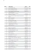
Summary of Contents for 37x2

Page 1: ...OWNERS S MANUAL 37x2 Drum Sander Shown With Optional Infeed Outfeed Tables DRO Abrasive Storage and Casters...

Page 2: ...na Tools machine for your shop Regards Torben Helshoj President Founder Laguna Tools This manual applies to the 37x2 double head drum sanders Enter the model number serial number and purchase informat...

Page 3: ...s 16 Using The Depth Gauge 17 Selecting Drum Abrasives 18 Tips For Maximum Performance 19 TROUBLESHOOTING Troubleshooting Guide Motors 21 Troubleshooting Guide Machine 22 Troubleshooting Guide Operati...

Page 4: ...REN AWAY All visitors should be kept safe distance from work area 6 MAKE WORKSHOP KID PROOF with padlocks master switches or by removing starter keys 7 DON T FORCE TOOL It will do the job better and s...

Page 5: ...in 17 USE RECOMMENDED ACCESSORIES Consult the owner s manual for recommended accessories The use of improper accessories may cause risk of injury to persons 18 NEVER STAND ON TOOL Serious injury could...

Page 6: ...6 Main Components Fig 1 Main Components Tension Rollers Height Adjustment Handle ON OFF switch Conveyor motor Intellisand switch Main motor drums...

Page 7: ...he SUPERMAX one each for the right and left column tubes Important These set screws are tightened for shipping and must be loosened and readjusted before operating either the height adjustment mechani...

Page 8: ...Extension cords are not recommended but if used should be of at least 10 gauge wire for lengths up to 10 and of at least 8 gauge wire for longer lengths Views of junction box under conveyor motor with...

Page 9: ...r best results follow the recommendations of the manufacturer of your dust collection equipment CHECKING DRUM ALIGNMENT Your SUPERMAX was shipped from the factory preadjusted with the drum s aligned t...

Page 10: ...stment indicators to zero on both sides Toset loosen the hex nut then moving the indicator scale so that the zero mark is directly under the pointer and retightening the hex nut see Fig 7 Likewise zer...

Page 11: ...ustment besuretoloosenbothoftheset screwslocatedon the front of bothtable support castings see Fig 3 and Fig 9 to allow the table support to slide on Fig 9 Table height adjustment both column tubes Th...

Page 12: ...the trailing edge of the wrap properly cut rewrap the drum and insert the tapered end through the slot in the right inboard end of the drum Insert the tapered end into the inboard take up fastener Pu...

Page 13: ...nstall Fig 10 d Insert tapered end into outboard slot Fig 10 e Wrap around drum without overlap Fig 10 f Mark wrap where it crosses drum edge Fig 10 g Insert tapered end into inboardslot Fig 10 h Allo...

Page 14: ...gin to use the SUPERMAX Thebasicoperating procedure forall of the SUPERMAX models is asfollows 1 Set depth of cut 2 Start drum s 3 Start conveyor and select feedrate 4 Start dust collector system 5 Fe...

Page 15: ...but either the primary or secondary drum can be used alone Front Drum To adjust the front drum set the drum height equal to the thickness of the piece to be processed Thisismosteasilydoneasfollows Lo...

Page 16: ...h of sanding Aslowerfeedrateprovidesmorerevolu tions of the drum per inch of sanding to allow a greater depth of cut and smoother sanding TheIntellisandcontrol SeeFig 13 continuously monitors the load...

Page 17: ...rapped with abrasive touches the con veyortable Make sure the indicator is laying snug on the table support casting Loosenthe knob holding the top of thickness scale and adjust the scale to zero Tight...

Page 18: ...e toburnish ing because of its open pores Selecting Grit Combinations The chart shown is a general guide to consult when selecting grits to use on dual drum machines and setting the rear drum This cha...

Page 19: ...eces thicker than 3 4 should be longer than the minimum normally recommended to prevent tipping of the stock see Specifications Goingtolongerpieces is especiallyimportantwhensandingboxesor other tall...

Page 20: ...o 1 hour then using a brush to remove any build up orburns Drytheabrasivestripscompletelybefore reuse In some cases build ups resulting from burns can beremoved with Plexiglas held on edge over a rota...

Page 21: ...MOTORS Problem PossibleCause Solution Motors do not start 1 Main power cord Plug in primary power unplugged from receptacle cord 2 Circuit fuse blown or circuit Replace fuse or reset breaker tripped b...

Page 22: ...t collection 4 Inadequate abrasive 5 Stockfedat 90 angle to drum Reduce depth of cut Use slower feed rate Increaseairflow at dust ports Use open coat abrasive Anglestocktoavoidresin line build up Conv...

Page 23: ...djust belt rollers misaligned 3 Conveyor table not flat Readjust by leveling with and square leg glides 4 Conveyor belt worn or Replace conveyor belt defective 5 Roller bushings elongated Replace bush...

Page 24: ...ar motorstalling ExcessiveV belttension Set screw loose on shaft couplerbetweengearmotor and conveyor tighten Conveyor bushings dry lubricate Rippled sanded surface uniformly spaced ripples 1 Excessiv...

Page 25: ...asive strips 4 Abrasive is too fine 5 Abrasivestrips overlapped 6 Drum out of alignment Increase feed rate Reduce depth of cut or increase grit coarseness Reduce depth of cut cleanstripsorreplace Repl...

Page 26: ...er adjustments may be necessary as outlinedbelow Followingthesestepsshouldresult in smooth operation Readjustment Procedure 1 Loosen the set screws located at the front of the table support castings F...

Page 27: ...smooth and even If not adjust the gears for good mesh Fig 18 Measure the space between the miter gear and the adjusting screw support that holds the height adjusting screw in place Fig 19 The distance...

Page 28: ...r the feed table has been lev eled loosenallfourtensionrollersuspensionbolts Fig 22 Comparing drum support casting heights see Fig 26 Raise the tension roller suspension assembly to its highest positi...

Page 29: ...rom the back side of the machine Again adjust the contact between the drum and guide so the drum can barely be turned by hand Measure at both sides of the drum to check that the secondary drum is para...

Page 30: ...width of the board approxi mately 2 1 4 from the end of the board If a snipe mark occurs on the trailing end of the board adjust the infeed tension roller Tensionroller pres surecanbeadjustedtwoways...

Page 31: ...r re installation Note If the conveyor belt continually tracks to one side of the machine first try reversing the belt on the conveyor bed If this doesn t remedy the problem place a level on the conve...

Page 32: ...lt and replace it with the newV belt Machine Reassembly 1 Toreassemble the unit after replacing the V belt first place the transfer rod back through the machine Tighten the shaft collar Reinstall the...

Page 33: ...Lift control board from housing Install the new controller referring to the correct electrical diagram and reverse the disassembly procedure Toreplace the on off switch remove the two screwsholdingcov...

Page 34: ...30 5206 2 13 SUPPORT ADJUSTING SCREW 30 1112 2 14 SUPPORT OUTBOARD TABLE 30 5204 1 15 HEX NUT 5 16 18 12 0003 4 16 FLAT WASHER 5 16 11 0206 4 17 BRASS TIPPED SET SCREW 5 16 18X3 4 10 9906 4 18 KNOB L...

Page 35: ...1101 1 2 38 BASE SUPPORT BRACKET 40 4241 1 39 RETAINING RING E12 20 0752 1 40 OUTBOARD HEIGHT ADJ SCREW 30 1211 1 41 BEARING R8ZZ BB R8ZZ 3 42 KNOB 913002 142 1 44 E RING E10 635DS 139 1 45 SPRING WAS...

Page 36: ...36 SUPERMAX STAND ASSEMBLY...

Page 37: ...16 18X1 10 1204 6 15 HEX CAP SCREW 5 16 18X1 1 4 10 9106 2 16 FLAT WASHER 5 16 11 0206 10 17 SPACER 5 16 I D 30 1305 2 18 BEARING 50 3067 4 19 OUTBOARD DRUM MOUNT BRACKET 40 0519 1 20 HEX NUT 5 16 18...

Page 38: ...1038 1 50 PHILLIPS FILLISTER HEAD SCREW 8 32X1 10 3107 6 51 COMPRESSION SPRING 20 3268 6 52 CARRIAGE BOLT 5 16 18X3 4 10 1203 4 53 FLAT WASHER 3 16 913002 253 2 54 TENSION ROLLER BASE BRACKET 40 0306...

Page 39: ...39 SUPERMAX DUAL DRUM HEAD ASSEMBLY...

Page 40: ...13 SIDE RAIL RIGHT 40 4144 1 14 ROLLER SUPPORT BRACKET 635DS 338 1 15 DRIVEN ROLLER 30 3107 1 16 HEX CAP SCREW 3 8 16X3 4 480BS 177 4 17 FLANGE LOCK NUT 3 8 16 12 0209 16 18 CONVEYOR BED 40 4201 1 19...

Page 41: ...30 3102 1 45 CARRIAGE BOLT 5 16 18X1 10 1204 4 46 MOTOR 5HP 1Ph 70 0507 1 47 HEX NUT 10 32UNF 480BS 216 2 48 SPRING WASHER 5 16 480BS 167 4 49 LOWER INNER BELT GUARD 40 1000A 1 50 LOCK WASHER M6 635D...

Page 42: ...S 350 3 66 STRAIN RELIEF PG 21 PG 21 1 67 JUNCTION BOX 913003 354 1 68 RUBBER BUSHING D25 PLAREVO1216 205 1 69 SCREW M4X0 7X6 913003 356 4 70 SCREW M6X1 0X8 913003 357 4 71 SCREW M5X0 8X8 913003 361 1...

Page 43: ...43 CONVEYOR MOTOR...

Page 44: ...tions Conveyor Motor Direct driveDC motor Infinitelyvariablefrom0to15feetperminutewithIntellisand Conveyor Belt 100 grit abrasive conveyor belt included Drive Motor 5 HP TEFC 1 PH 1 740 RPM 208 230 vo...

Page 45: ...45...

Page 46: ...46 NOTES...

Page 47: ...boards stock glue removal 60 7060 60 9060 60GRIT Surfacinganddimensioningboards trueingwarpedboards 60 7080 60 9080 80 GRIT Surfacing light dimensioning remove planer ripples 60 7100 60 9100 100 GRIT...

Page 48: ...D BELT GUARDING IN PLACE KEEPHANDSANDCLOTHINGAWAYFROMOPERATINGDRUM S BELT AND PULLEYS ALWAYSMAINTAIN CONTROL OF STOCK TO AVOID KICKBACK KNOW HOW TO PREVENT IT ALWAYSDISCONNECT ELECTRICAL POWER BEFORE...

Reviews: