


52
9.
Restart the saw and check that it stops when you press another
emergency button.
10.
Repeat the procedure with all the emergency buttons. Repeat the
procedure for the shaper, mortiser and jointer/planer.
11.
With the shaper running, open the door to the motor. The power
should be removed from the motor, and it will slow down.
12.
With the jointer running, unlock the table and slowly lift. There is a
micro switch that will operate and remove the power from the motor.
13.
Set the machine in planer configuration.
14.
Start the planer as described earlier in the manual.
15.
With the machine running, lift the dust chute until the safety micro
switch operates. The motor should have the power removed and slow
down.
16.
If any of the safety switches fails to operate correctly, do not use
the machine until the fault has been corrected.
Before you cut any wood, read the safety rules at the front of
this manual.
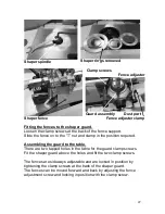
Using and adjusting the machine.
Adjustments.
Note.
The machine has had all its functions calibrated at the factory,
but some movement may have taken place due to shipping
conditions. This is unavoidable, and it is recommended that the
following checks are made prior to starting production. As the
machine is used, some functions may move, and it is, therefore, good
practice to know the process for adjusting the machine prior to
production.
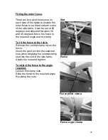
Fine-tuning the miter fence.
Several methods are acceptable to fine-tune the fence, but we have
found that the following is a very practical way to achieve a square
panel:
1.
Clamp the fence locked at 90 degrees.
2.
Clamp a sheet onto the sliding table and cut a straight edge (“A”).
Mark “A.”
3.
Move the sheet so that edge “A” is tight against the fence, clamp in
position, cut edge “B” and mark “B.”
Summary of Contents for MCO8000-0250
Page 2: ......
Page 9: ...9 Parts of the machine 12 10 11 8 9 13 ...
Page 14: ...14 What you will receive with the machine Support table Mortiser unit ...
Page 15: ...15 10 9 8 7 6 5 4 3 2 1 11 12 13 14 15 16 17 18 19 20 21 22 23 24 25 26 27 28 29 30 31 32 33 ...
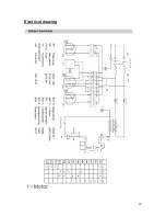
Page 67: ...67 Electrical drawing ...
Page 68: ...68 ...
Page 69: ...69 Revised wiring diagram for later machines ...
Page 70: ...70 ...
Page 71: ...71 Exploded view drawings and parts list ...
Page 72: ...72 ...
Page 73: ...73 ...
Page 74: ...74 ...
Page 75: ...75 ...
Page 76: ...76 ...
Page 77: ...77 ...
Page 78: ...78 ...
Page 79: ...79 ...
Page 80: ...80 ...
Page 81: ...81 ...
Page 82: ...82 ...
Page 83: ...83 ...
Page 84: ...84 ...
Page 85: ...85 ...
Page 86: ...86 ...
Page 87: ...87 ...
Page 88: ...88 ...
Page 89: ...89 ...
Page 90: ...90 ...
Page 91: ...91 ...
Page 92: ...92 ...
Page 93: ...93 ...
Page 94: ...94 ...
Page 95: ...95 ...
Page 96: ...96 ...
Page 97: ...97 ...
Page 98: ...98 ...
Page 99: ...99 ...
Page 100: ...100 ...
Page 101: ...101 ...
Page 102: ...102 ...
Page 103: ...103 ...
Page 104: ...104 ...