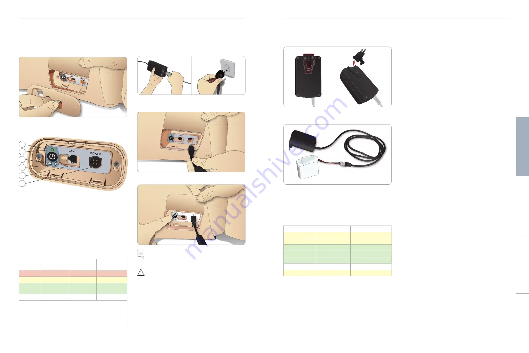
laerdal SimMan 3G User Manual Download Page 8

The Power Panel

The power panel is found on the right side of the Patient Simulator, 
under a loose skin flap.  Lift the skin flap and pull out the protective 
cover.

To ensure easy access, use the zippered clothing provided with the  
Patient Simulator.

DC Input 9-24V X, XA

1

2

3

4

5

6

Power panel overview

1  Power ON / OFF button

2  Power status indicator

3  Battery status indicator

4  Charging status indicator

5  LAN network cable connector

6  External power supply connector

Power Status Indicator Description

Indicator
Light Color

Power Status

Battery Status

Charge Status

Red

Power save*

0% - 20%

Not charging**

Yellow

Start up

20% - 70%

Charging

Green

Running

70% - 100%

Charge almost 

complete***

No light

Off

Off

No charge****

* Blinking light
** One or both batteries missing, overheated, damaged or 
otherwise not able to charge
*** Not recommended to charge the batteries too long
**** No power input, batteries are charged.

Power Save is activated whenever Patient Simulator is paused.

Charging the Batteries

Inside the Patient Simulator

1  Connect the Patient Simulator to the external power supply 

with a power cord and plug that meets local specifications.

2  Plug the power supply into a wall outlet and connect the power 

cable to the power inlet on the Patient Simulator’s power panel.

POWER

3  Press the ON button to power on the Patient Simulator.

 Note: During startup, the Patient Simulator’s eyes will blink and the 

power status indicator light will be yellow.  


Caution: After Patient Simulator is turned off, wait 20 seconds 
before restarting. If not, Patient Simulator may not function properly.

14

15

SETUP


SETUP


External Battery Charging

The battery charger comes with 5 international plugs. Connect the 
appropriate plug to the charger:

1  Connect the charger to a power outlet and connect the Patient 

Simulator battery to the charger.

2  The indicator light on the battery charger shows charge status.

3  Battery charging time is approximately 3 hours.

The external battery charger should only be used with 

SimMan 3G


batteries.

Charger light showing battery sign

Light Code

Light Color

Characteristic

Standby

Yellow

Steady

Pre-charge

Yellow

Normal Blink

Rapid charge

Green

Rapid

Maintain

Green

Normal Blink

Ready

Green

Steady

Wait

Alternating

Alternating

Error

Yellow

Rapid

Battery Use

− 

Always use two SimMan3G batteries to power the Patient 
Simulator

− 

Ensure that the batteries are properly connected

− 

Charge the batteries regularly

− 

Check LEDs on Patient Simulator’s power panel for battery 
status


– Change both batteries before the battery charge drops below 

15% or the battery light indicator is red. This can be monitored 
in the technical status window on the Instructor PC


– The Patient Simulator will automatically shut down if: Battery 

temperature rises above 60°C (140°F) or the remaining charge 
falls below 6 % on one of the two batteries

View Battery Status in LLEAP

Check the power indicator in the Simulator Status window in LLEAP
according to the instructions in LLEAP Help.

Changing Batteries during a Simulation Session:

1  Press <Pause Session> on Instructor PC.  Access the batteries as 

described in 

Inserting and Connecting the Batteries

2  Replace one battery at a time to avoid loss of simulation data

Storage  and Transportation

− 

Never store fully charged batteries for longer than a month

− 

Never store the batteries inside the Patient Simulator

− 

Store batteries in a refrigerator i.e. temperature 0°C - 4°C 
(32°F - 40°F)

− 

The two simulator batteries can be transported in the Patient 
Simulator during air freight

− 

When transporting spare batteries please contact the airline or 
freight company for the latest transport regulations

Battery Maintenance

− 

On approximately every 30th charge cycle, drain the battery 
completely before recharging. To drain the batteries, run the 
Patient Simulator on both batteries until automatic shutdown

− 

Expected battery life: 200 charge cycles

− 

Replace only with Laerdal SimMan3G batteries

Cautions 

and 

W

arnings

Featur

es

Setup

Maintenance

Spar

e Par

ts

Tr

oubleshooting

Summary of Contents for SimMan 3G

Page 1: ...SimMan 3G User Guide www laerdal com EN...

Page 2: ...LLEAP 22 RFIDTag Setup 23 Using RFIDTags 23 Connecting Defibrillation Adapter Plates 24 Connecting the Blood Pressure Cuff 25 Calibrating the Blood Pressure Cuff Using LLEAP 25 Connecting the SpO2 Pro...

Page 3: ...the internal tubing and cabling is disconnected Never use the Patient Simulator outdoors in wet conditions as this may pose a shock hazard or damage the simulator Never use the Patient Simulator in te...

Page 4: ...ulation session comprises the following main applications LLEAP Laerdal Learning Application Voice Conference Application Patient Monitor SimView Server or SessionViewer SimDesigner and other applicat...

Page 5: ...geal swelling Laryngospasm Decreased cervical range of motion Trismus Teeth soft upper dentures may be replaced with a hard set of teeth for enhanced realism while practicing intubations During simula...

Page 6: ...can be made See LLEAP Help for further information Sounds Two types of sounds can be used in a scenario Body sounds Vocal Sounds The sounds can be triggered by the scenario or controlled by the instr...

Page 7: ...the clips on either side 2 Insert both batteries into the battery tray 3 Snap the battery clamp back into place over the batteries 4 Connect the corresponding battery cables from the batteries to the...

Page 8: ...arging time is approximately 3 hours The external battery charger should only be used with SimMan 3G batteries Charger light showing battery sign Light Code Light Color Characteristic Standby Yellow S...

Page 9: ...Patient Simulator is stationary over extended periods of use If the Patient Simulator is required to exhale CO2 with each ventilation connect external CO2 Connect CO2 only if the Patient Simulator is...

Page 10: ...he button will light and blood will flow into the Patient Simulator 4 Charge the system for 60 seconds before starting bleeding simulation Warning Connecting a full blood fill unit to a Patient Simula...

Page 11: ...this process for as many times as is necessary Note If the external fill unit runs empty during a bleeding scenarios air will be introduced to the blood system causing inaccurate reading The IV Cathe...

Page 12: ...carry an RFID tag RFID tagging Syringes Airway Devices The RFID tags come as part of the SimMan 3G Drug and Airway Tag Kit Tags are pre printed with information to identify drugs drug concentration or...

Page 13: ...not defibrillate the Patient Simulator without the torso skin Warning Do not defibrillate the Patient Simulator in a flammable or oxygen enriched atmosphere Warning The Patient Simulator torso must a...

Page 14: ...e soft set may be replaced with a hard set of teeth 1 Remove the teeth from the mouth 2 Align the new set of teeth with the gums and push them back until the teeth engage and lock onto the gums 3 Ensu...

Page 15: ...default leg OpenTorso Skin and stomach foam as shown in Maintenance 2 Unscrew hip joint connector Remove the leg cables and tubes from the connector 3 Carefully remove the left leg with cables and tub...

Page 16: ...obility Note The SimMan 3G System exceeds the weight allowance on most commercial airlines Some parts may have to be transported separately For more information on weight restrictions contact the rele...

Page 17: ...flushed with isopropanol press fill the button again to deactivate the filling of isopropanol to the reservoir The LED indicator on the fill button will now be off 13 Leave the isopropanol fill bottl...

Page 18: ...a new router attach the power cable to the DC plug and the Ethernet cables back into the router again Opening theTorso Open the Patient Simulator torso for the following procedures Attaching or Repla...

Page 19: ...5 Tighten the shoulder screw with the Allen wrench LAPULSES BP LACONV P B L BP PULSES L L LA B 6 Connect the arm cables to the corresponding connection points in the torso Left Arm toTorso Cable andT...

Page 20: ...ns the bladders may need replacement 1 Open theTorso Skin to expose the chest plate Lift the chest plate to reveal the pneumothorax bladders located in slots in the side of the chest plate assembly 2...

Page 21: ...skins easier To prevent the zippers from separating from the skin make sure to properly position the skin halves and hold them together while zipping them closed Replacing Blood System Filter If reduc...

Page 22: ...d or are leaking See Opening the Torso In case of fluid leakage power off the Patient Simulator and contact LaerdalTechnical Service Problem Identifying a single Patient Simulator when there are multi...

Page 23: ...nt Simulator internal pkg 2 212 12350 Thigh joint connector 212 12450 Battery clip Patient Simulator internal 212 12550 Panel cover left and right 381107 SoftTeeth 212 14250 Arm Adaptor SimMan SimMan...

Page 24: ...20 07890 Rev D 2016 Laerdal Medical AS All rights reserved Manufacturer Laerdal Medical AS P O Box 377 Tanke Svilandsgate 30 4002 Stavanger Norway T 47 51 51 17 00 www laerdal com...

Reviews: