INSTRUCTIONS FOR THE INSTALLER
8
2.
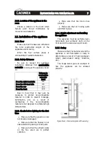
Key to casing diagram:
1 Ceiling
2 Flue
3 Incombustible material (Inner hood
insulation)
4 Insulating deflector made of
incombustible material
5 Wall
6 Fresh-air inlet (1,000 cm
2
)
7 Hot-air outlet (1,000 cm
2
)
Figure No.5 -
Exterior diagram of the casing
In order to enable suitable air
circulation and correct operation, the
casing must have a fresh-air inlet with a
minimum section of 1,000cm
2
beneath the
level of the actual appliance and a hot-air
outlet measuring at least 1,000cm
2
above
it (just before the insulating deflector
inside the casing). These inlet and outlet
sections must ensure air renewal in such a
way as to avoid damage to parts inside the
hood due to excess temperature.
A further hot-air ventilation grille is
also recommended between the insulating
deflector on the hood and the ceiling.
On non-central-heating appliances
(without back boiler), Lacunza does not
recommend enveloping the outside of
appliances with insulation.
The installer must fit the necessary
inspection accesses (trap doors, hatches,
etc.) so that everything inside the hood
that may need maintenance work or
replacement can be accessed at any time,
e.g. counterweight system, hydraulic
components, heating circuit safety
components.
2.3.6.
Connection to the flue
The appliance must be connected to
the chimney flue using special piping
designed to resist the products of
combustion
(e.g.
stainless
steel,
enamelled steel, etc.).
To connect the flue to the socket
flange, insert the piping inside the flange
and seal the joint with fire sealant or fire
cement to make it completely airtight.
The installer must ensure that the pipe
connected to the appliance is well secured
and there is no chance of it coming free
from its housing (e.g. as a result of
dilatation due to temperature, etc.).
2.3.7.
Piping air to other rooms (Andrea
/ Abodi)
It is possible to pipe some of the heat
generated to other rooms in the house
using the appliance. This does not mean
that the appliance works more efficiently,
but it does mean that the heat it creates is
distributed better. For this purpose, in the
top surface of the appliance there are 2
potential hot-air outlets with diameters of
120mm on the top shell of the appliance.
Pipes can be fitted from these outlets to
other rooms. If you intend to do this, bear
the following points in mind.
Do not break the scored steel
circles completely. Simply bend them in
order to facilitate the conduction of
heat to the pipe.
Summary of Contents for Sara
Page 1: ...Sara Lorea Abodi Andrea Instruction Book...
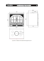
Page 6: ...PRESENTATION OF THE APPLIANCE 5 1 Figure No 2 Dimensions of the Abodi Andrea appliance in mm...
Page 19: ...BASIC BREAKDOWNS 18 6 BASIC BREAKDOWNS 6 NO TRADUCIR EL TEXTO DE ESTA IMAGEN...
Page 21: ...DECLARATION OF PERFORMANCE 20 7 DECLARATION OF PERFORMANCE 7...
Page 22: ...DECLARATION OF PERFORMANCE 21 7...
Page 23: ...DECLARATION OF PERFORMANCE 22 7...
Page 24: ...DECLARATION OF PERFORMANCE 23 7...
Page 25: ...CE MARK 24 8 CE MARK 8...
Page 26: ......


