6
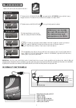
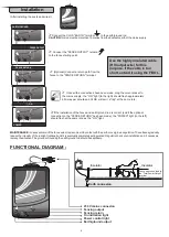
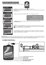
FUNCTIONAL DIAGRAM :
ON
(After installing the posts and wires !)
Ø
Connect the CLOS "EARTH" terminal to the earth/ground rod.
CAUTION
, this rod must be more than 10 metres from the domestic earth of the mains supply.
Ø
Connect the "FENCE OUTPUT" terminal
to the fence starting point.
Ø
(Optional) Connect a return path from the
fence to the "FENCE RETURN" terminal.
Ø
the mains supply : the "ON" light (to the right) should flash approximately
40 times per minute and CLOS will emit a "tap" at the same rate.
Once all the connections have been made, plug the curent socket to
Ø
If the installation of the fence and earth/ground rod is correct (and if the optional
connection to the "FENCE RETURN" has been made), the "POWER" light (to the left)
should flash at the same rate as the "ON" light.
POWER
230 V mains connexion
Fencing output
Fencing return
On indication light
Power control light
Earth/ground output
Installation
EARTH/GROUND
FENCE OUTPUT
FENCE RETURN
Use the highly insulated cable
(HV output wire) for this
purpose. If the cable is too
short, extend it using the FISOL.
Earth connexion
Fence wire connected to
the “Total Power Output”
terminal
Insulator
Insulator
MAINTENANCE :
Losses will occur if the fence wire or tape comes into contact with the earth
or overgrown vegetation. These losses gradually
reduce the intensity of the red light (optional) until it is eventually completely extinguished. Regularly check your installation and, if necessary,
remedy the situation. The ground surrounding the earth/ground rod should be kept damp.
Summary of Contents for CLOS 100
Page 2: ......

