


LaCie 12big rack network
Installation
Quick Install Guide
page 5
Battery Safety
2.5.
replacing batteries on the motherboard.
Please refer to the battery replacement procedure in the 12big
rack network User Guide supplied with your system.
Warning:
There is a danger of explosion if the battery is
replaced by an incorrect type.
Dispose of used batteries in accordance with the
manufacturer’s instructions and national regulations.
Caution:
The batteries on the NVRAM Card are not replace-
able; the complete card assembly must be replaced in the event
of battery failure. Refer to the 12big rack network User Guide for
the card replacement procedure.
Fitting Drives
2.6.
Warning:
Operation of the enclosure with ANY drive carrier
modules missing will disrupt the airflow and the drives will not
receive sufficient cooling. It is essential that all apertures are
filled before operating the unit. Dummy drive carrier modules
are available for fitting to unused drive bays.
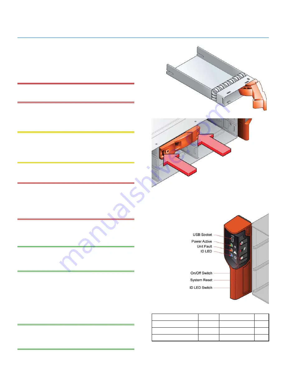
Release the carrier handle by pressing the latch in
1.
the handle towards the right and insert the carrier
into the enclosure.
iMPortant:
Ensure that the carrier is orientated so that the
drive is uppermost and the handle opens from the left
(See
Figure 5).
Slide the carrier, gently, all the way into the enclosure.
2.
Cam the carrier home - the camming foot on the
3.
base of the carrier will engage into the slot in the
enclosure.
When the carrier is fully home, close the handle - a
4.
click should be heard as the latch engages.
iMPortant:
Ensure that all drive carriers are fully engaged in
the enclosure by firmly pushing each one home fully into the slot
(See Figure 6).
Figure 5:
Drive Carrier Module
Note: Ensure that the handle always
opens from the left.
Figure 6: Fitting Drives
Note: Ensure that the carriers are fully engaged in the enclosure.
Operator Panel
2.7.
LeD
Color
normal
Fault
Power On
Green
On
On
Fault
Amber
Off
On
Enclosure ID
Blue
N/A
N/A
Figure 7: operator Panel