INSTALLER’S MANUAL
CORMATIN
Page 6 of 40
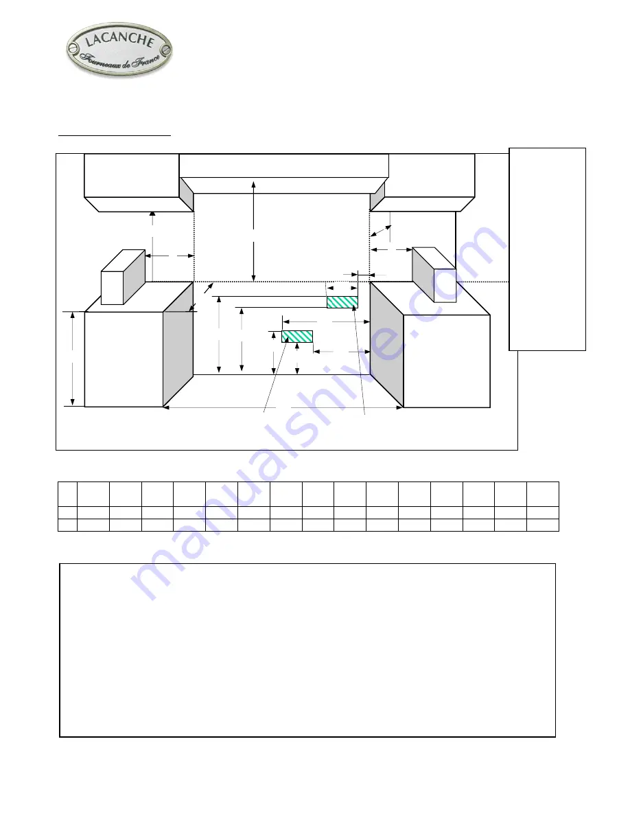
Cabinet preparation
:
A B C D E F G H I J K L M N O
mm
762 330
457 914 290 420 235 405 20 60 765 865 705 51 660
’’
30 13 18 36
11
7
/
16
16
9
/
16
9
1
/
4
15
15
/
16
13
/
16
2
3
/
8
30
1
/
8
34
1
/
16
27
3
/
4
2
26
The range is a freestanding unit. If the unit is to be placed next to cabinets, the clearances shown in Figure 4
are required.
The top grate support must be 34 mm - 1
5
/
8
’’ above the adjacent base cabinet countertop.
Min clearances to combustibles:
2 3/4’’ (70 mm) from rear of range to wall. This requirement will be met when range is installed with
factory supplied back spacer vent (or equivalent).
0 ’’ (0 mm) from sides below 36’’ (914 mm) height.
2’’ (51 mm) from sides above 36’’ (914 mm) height.
Cabinets 13’’ (330 mm) deep may be installed above the range at least 30’’ above the plane of the cooking
surface.
Use range only with factory supplied legs
NOTE: The above diagram depicts the actual location of gas and electrical connections on the range. DO NOT
place gas stub-out or electrical receptacle in these areas. Place them nearby in accordance with local
regulations.
G
C
N
Gas connection
Electrical
connection
Fig. 4
B
D
E
F
H
K
I
J
L
M
N
A
O
This diagram
depicts the
actual location
of gas and
electrical
connections
on the range.
Place gas
stub-out or
electrical
receptacle
outside of this
area in
accordance
with local
regulations.


