background image

INSTALLER’S MANUAL


CORMATIN


Page 21 of 40 


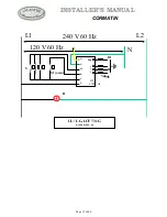
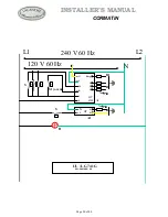
H

240 V 60 Hz

120 V 60 Hz

L2

N

L1

4

3

1

2

5

TH

H1

TL

31              32
21              22
11              12

K
M

KM

A2

H

R1

A1

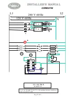
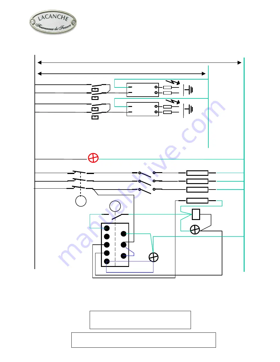
UL / LG 741 E

Réf. S001010 – 00

HT

N

4

L

5

HT

N

4

L

5

A1

A1

S

B

B

R1

R

R

S2

P2

P1

P3

N. B : For the model LG/LCF 731 E, the ignition connector which is not 
used is connected to earth. 

Summary of Contents for Cormatin

Page 1: ...bor s phone Follow the gas supplier s instructions If you cannot reach your gas supplier call the fire department Installation and service must be performed by a qualified installer service agency or...

Page 2: ...heating plate Gas oven Enameled sheet metal Dimensions W x H x D 530 mm 20 8 x 305 mm 12 x 460 mm 18 1 4 shelf level with 62 mm spacing 55 liters 2 18 ft3 Heating provided by thermostatically controll...

Page 3: ...idth Depth Height mm Weight Gross Net LG 731 G 850 mm 33 4 840 mm 33 1 1070 mm 42 1 105 kg 89 kg 233 197 lb Gas connection 1 2 ID NPT Sch 40 inlet on male coupling Figures 1 2 and 3 Sealant on all pip...

Page 4: ...TECHNICAL DATA CORMATIN Page 4 of 40 UF SF T I SF F F SF F F...

Page 5: ...in a workmanlike manner in accordance with the instructions in this manual and locally applicable regulations In the Commonwealth of Massachusetts the appliance must be installed by a licensed plumbe...

Page 6: ...th factory supplied back spacer vent or equivalent 0 0 mm from sides below 36 914 mm height 2 51 mm from sides above 36 914 mm height Cabinets 13 330 mm deep may be installed above the range at least...

Page 7: ...S L P propane 10 WC THE APPLIANCE MUST BE INSTALLED IN ACCORDANCE WITH THE LOCAL CODES OR National Fuel Gas Code ANSI Z223 1 or latest edition In the Commonwealth of Massachusetts the appliance must b...

Page 8: ...in the right rear corner under the hob to gain access to the pressure regulator remove the top The reversible cap is labeled either LP or Nat and is easily recognized by the raised center screw slot f...

Page 9: ...ace by a transversal bar H fig 16 In order to take them out unscrew screws I fig 17 then G fig 15 Note When one or more nozzles are changed the sealing ring should be changed as well see gas circuit d...

Page 10: ...nging from maximum setting to minimum setting Refitting the cooking surface When refitting the cooking surface it is vital to tighten fastening screws figures 7 8 and 9 Failure to do so can cause dist...

Page 11: ...4 Adjustment of oven selector Adjustment is VITAL after connection or any change of gas When the range is installed be sure that this selector cartridge Fig 23 and 24 is turned all the way to the pro...

Page 12: ...ed for 30 A 125 250 VAC type SRD SRDT S SO or ST Where local Codes do not permit grounding through neutral use a 4 wire power supply cord or pigtail kit Cord must be agency approved for use with house...

Page 13: ...k spacer vent onto these brackets by using the washers and nuts supplied with the range STABILITY DEVICE INSTALLATION INSTRUCTIONS Screw the anti tip bracket T to the wall according to figures 30 31 3...

Page 14: ...e 4 Grease the tap shaft High temperature lubricant for example SILICAL GEL BARBAHL Caution Any excess grease should be removed Reverse operation 3 to 1 in that order to put valve and knob back on Lim...

Page 15: ...0 kW 65 064007 Injector holder 65 033018 Sealing ring 65 430007 Injector Dia 65 65 14964 Injector Dia 90 65 14969 Injector Dia 95 65 14970 Injector Dia 105 65 52863 Injector Dia 120 65 14973 Injector...

Page 16: ...of 40 65 330008 65 330005 65 103023 65 430007 65 222002 65 103021 65 224004 65 222003 65 224005 80 903277 65 103022 65 226003 65 226006 65 080005 1 5 kW 65 064007 3 0 kW 65 064007 5 0 kW 65 064007 65...

Page 17: ...of 40 65 430007 65 222002 65 103021 65 224004 65 222003 65 224005 88 265400 65 103022 65 226003 65 226006 65 080005 1 5 kW 65 064007 3 0 kW 65 064007 4 0 kW 65 064007 65 033018 65 103023 65 103021 65...

Page 18: ...2003 65 222003 65 222003 65 222003 S2 Thermostat switch 65 52194 65 52194 65 52194 A Spark Module 3 1 reign 65 226005 65 226005 65 226005 65 226005 A1 Spark Module 2 65 226002 65 226002 65 226002 65 2...

Page 19: ...INSTALLER S MANUAL CORMATIN Page 19 of 40 H L2 L1 N S1 oven S 120 V 60 Hz 240 V 60 Hz A B1 B HT 6548 UL LG LCF 731 G R f S001009 00 1 2 3 G N M R C L Reig...

Page 20: ...INSTALLER S MANUAL CORMATIN Page 20 of 40 H L2 L1 N HT N 4 L 5 1 2 3 G N M R C L Reig S1 oven S 120 V 60 Hz 240 V 60 Hz A A1 B1 B B S HT 6548 UL LG 741 G R f S001008 00...

Page 21: ...Hz 120 V 60 Hz L2 N L1 4 3 1 2 5 TH H1 TL 31 32 21 22 11 12 K M KM A2 H R1 A1 UL LG 741 E R f S001010 00 HT N 4 L 5 HT N 4 L 5 A1 A1 S B B R1 R R S2 P2 P1 P3 N B For the model LG LCF 731 E the igniti...

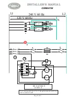
Page 22: ...120 V 60 Hz L2 N L1 TH H1 TL 31 32 21 22 11 12 K M K M M M KM A2 H HT N 4 L 5 HT N 4 L 5 S A1 A1 B B S2 A1 R2 R2 4 3 1 2 5 P2 P1 P3 UL LG 741 CT R f S001011 00 N B For the model LG LCF 731 CT the ign...

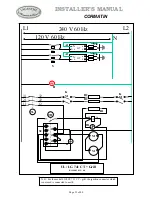
Page 23: ...0 Hz L2 N L1 P2 P1 P3 TH H1 TL 31 32 21 22 11 12 K M K M M M R1 KM A2 H S2 R2 R2 A1 4 3 1 2 5 UL LG 741 CT Grill R f S001012 00 HT N 4 L 5 HT N 4 L 5 S A1 A1 B B N B For the model LG LCF 731 CT grill...

Page 24: ...Page 24 of 40 This page intentionally left blank...

Reviews: