background image


Maintenance

 Section 5


Page 13 


MOBILE DEMOLITION PROCESSORS  

BUILD UP PROCEDURE 

continued

WEAR PLATE REPLACEMENT

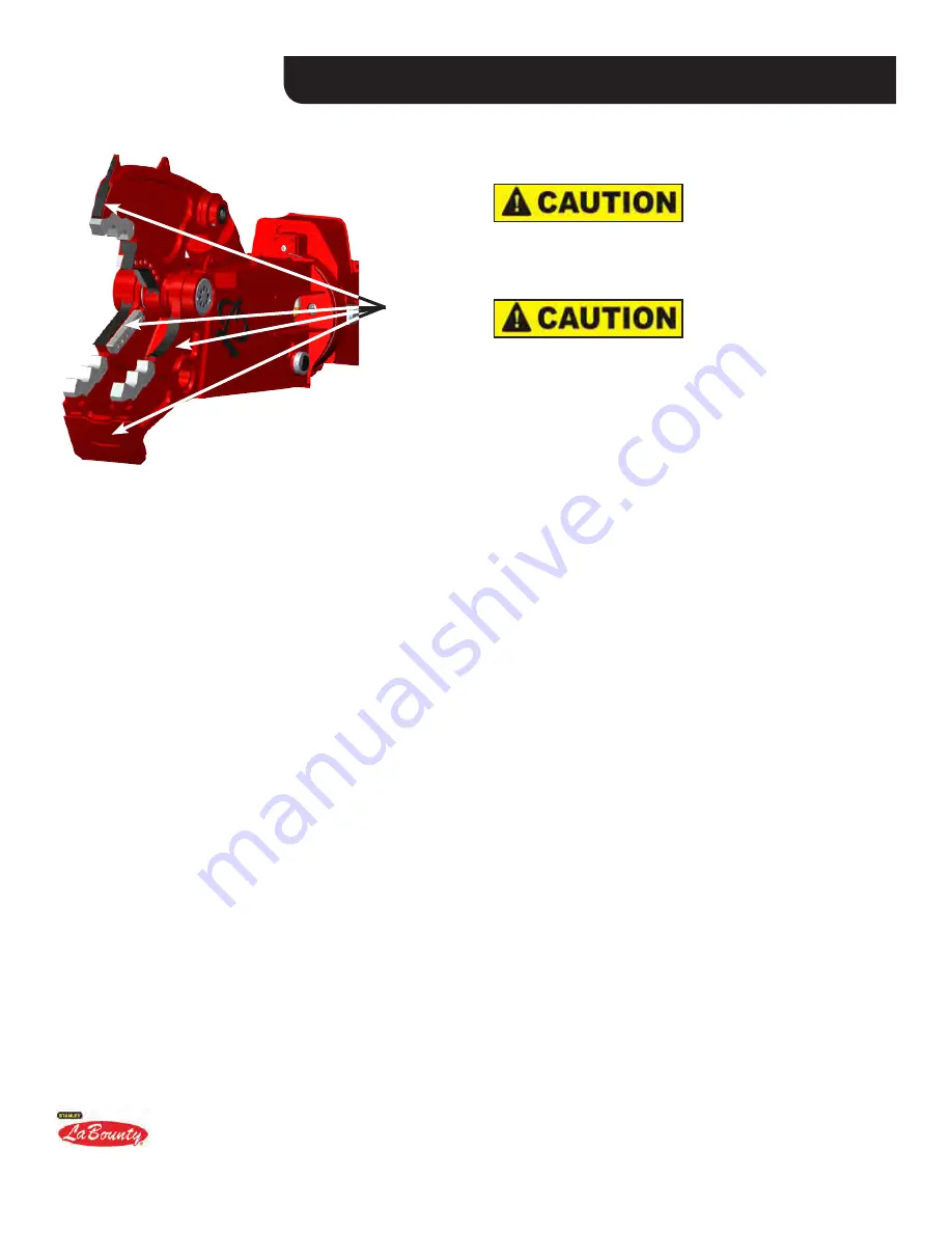
See Figure 5-5 for specific areas with wear plates installed; refer to Parts Catalog for specific wear plate part 

numbers. Pay special attention to the preheat and post-heat instructions and follow them exactly. 

1. Remove existing wear parts.

2. Clean the areas underneath old wear parts, removing any grease, paints, or other foreign materials that 

may be harmful to the weld.

3. Preheat the area to 200-300˚F (100-150˚C) and maintain this temperature throughout the build up and hard-

surfacing procedure.

4. If necessary, build up along the top and front edges of the secondary blade seat flush with the blade. The 

blade should not stick out beyond the edge of the seat in this area. However, do not weld in the apex area.
5. If the temperature within 6" (150 mm) of the weld area has dropped below 400°F (200°C) during the weld 

process, post heat this area to 400°F (200°C). 
6. Wrap with a heat blanket and allow the welded area to cool slowly to the ambient temperature. The MDP 

should not be put back into service until it has cooled completely.

7. If you have any questions, contact LaBounty Service Department (800-522-5059) for specific welding in-

structions.

HARDSURFACING RECOMMENDATIONS

If hardsurfacing, Stanley LaBounty recommends Amalloy 814H rod or equivalent. It is important to always 

use a hardsurfacing weld material with a chromium content of less than .10% ( or less than one-tenth of one 

percent) and a severe impact-resistance rating to prevent cracking. If you have questions about what hardsur-

face material to use, please contact the Stanley LaBounty Customer Service Department. Failure to adhere to 

LaBounty hardsurfacing recommendations may compromise the attachment warranty. Before hardsurfacing, 

E7018 underlayment beads must be laid down.  The hardsurfacing is then applied to the underlayment beads.  

Hardsurfacing must not be applied directly to the parent material.


Amalloy Welding and Industrial Supply 

Phone: 800-735-3040 (toll free) 

Fax: 763-753-8263 

Web site: amalloy.com 

FIGURE 5-5

WEAR 

PLATES

DO NOT use stainless hardsurface rod. It will 

crack the base metal, which can cause a major 
structural failure of MDP jaws.


Using improper build-up products may result 

in premature wear or increased potential 

for cracking and may compromise warranty 

coverage. 

Summary of Contents for 513914

Page 1: ...Mobile Demolition Processors Part Number 513914 Safety Operation Maintenance Manual...

Page 2: ...N This product is covered by one or more of the following patents U S PATENT NUMBERS 5 474 242 7 240 869 5 531 007 7 487 930 5 992 023 7 578 461 7 322 273 7 832 130 8 146 256 8 104 384 EPO Patent Numb...

Page 3: ...operty damage and personal injury The instructions in this manual have been prepared to ensure that when followed properly the attachment will provide efficient and reliable service Continuing product...

Page 4: ......

Page 5: ...ation 3 9 Hydraulic Start up Procedure 3 9 SECTION 4 OPERATION Before You Start 4 2 First Things First 4 2 General Rules for Safe Operation 4 3 Getting the Feel of the Attachment 4 3 Attachment Contro...

Page 6: ...ll Capacities 5 23 Turntable Bearing Lubrication 5 24 Turntable Bearing Lubricants 5 24 Hydraulic Requirements 5 25 Crossover Relief Flow Control Manifold 5 25 Motion Control Valve Manifold 5 26 Case...

Page 7: ...Introduction to Safety Section 1 Page 1 MOBILE DEMOLITION PROCESSORS SECTION 1 INTRODUCTION TO SAFETY Introduction 1 2 Understand Signal Words 1 2 Safety Summary 1 3 Attachment Decals 1 4...

Page 8: ...base machine and be sure that you understand all controls and operating instructions before attempting to operate this equipment Failure to follow the safety precautions can result in personal injury...

Page 9: ...stead of shearing The material being processed could become a projectile and cause injury or death DO NOT process any material in any position that may propel it toward operator other workers building...

Page 10: ...or component while it is pressurized Escaping fluid under pressure can penetrate the skin causing serious injury Relieve pressure before unhooking hydraulic or other lines See Figure 1 3 Tighten all...

Page 11: ...ety Section 1 Page 5 MOBILE DEMOLITION PROCESSORS STANLEY LABOUNTY BRAND DECALS REPLACEMENT DECALSAVAILABLE UPON REQUEST FIGURE 1 1 SAFETY FIRST DECAL PART NUMBER 503590 INCLUDEDWITH MANUALS FIGURE 1...

Page 12: ...Two Harbors MN 55616 tel 1 800 522 5059 fax 218 834 3879 www stanleyhydraulic com Made in the U S A with Global Materials Attachment Model Serial Number Year of Manufacture Weight ATTACHMENT DECALS c...

Page 13: ...About the Attachment Section 2 Page 1 MOBILE DEMOLITION PROCESSORS SECTION 2 ABOUTTHEATTACHMENT Attachment Model Description 2 2 Attachment Features 2 2 Jaw Options 2 3 Attachment Glossary 2 4...

Page 14: ...to draw the materials in to the point where the proceesor force is greatest making them the most efficient cutting tool possible MDPs can crush concrete and cut a wide variety of materials including I...

Page 15: ...About the Attachment Section 2 Page 3 MOBILE DEMOLITION PROCESSORS JAW OPTIONS CONCRETE CRACKER JAW CONCRETE PULVERIZER JAW FIGURE 2 2 FIGURE 2 3...

Page 16: ...PPER JAW FRONT CYLINDER PIN MDP CYLINDER MOUNTING BRACKET LINKAGE CONNECTION HYDRAULIC MANIFOLD BLOCK STICK CONNECTION MDP STICK APEX MDP LOWER JAW UPPER HEAD TURNTABLE BEARING HYDRAULIC MANIFOLD BLOC...

Page 17: ...the attachment The crossover is preset at the factory Valve and must not be tampered with Cylinder Hydraulic component that actuates the jaw set LaBounty cylinders are designed to withstand an extrem...

Page 18: ...excavator boom tip and stick cylinder Planetary Hydraulic rotation component on larger rotating attachments The planetary gear box rotates the body of the Gear Box attachment with the aid of the hydr...

Page 19: ...to the attachment Bearing stick and is driven by hydraulic components in the upper head of the attachment Upper Head Mounting bracket portion of the MDP Attaches to the turntable bearing that attache...

Page 20: ...Page 8 Section 2 About the Attachment MOBILE DEMOLITION PROCESSORS...

Page 21: ...ass 3 3 Third Member Attachment Mounting Procedure 3 3 Second Member Attachment Mounting Procedure 3 4 Third Member Attachment Removal 3 5 Second Member Attachment Removal 3 6 Attachment Storage 3 6 H...

Page 22: ...e properly rated hooks and rigging to lift the at tachment 2 Lift the attachment using all four hooking points with rigging lengths that keep the attachment level See Figure 3 1 Hooking points are for...

Page 23: ...unting bracket linkage connection see Figure 3 2 It may be necessary to use a lifting device overhead hoist forklift etc to correctly position the link 7 Pin the link to the linkage connection using t...

Page 24: ...mount it may be necessary to block the rear of the attach ment in a position to allow boom pivot pin installation NOTICE 5 Pin the excavator s boom and attachment boom pivot together using the same pi...

Page 25: ...ld See Figure 3 6 6 Plug the open manifold ports and hose ends with pressure plugs to prevent contamination of the MDP hydraulic system 7 At this point be extremely sure that the attachment is stable...

Page 26: ...e boom pivot pin from the attachment Figure 3 7 ATTACHMENT STORAGE 1 Securely block the attachment up off the ground using wood blocking 2 Plug all open hydraulic ports 3 Grease the pins and machined...

Page 27: ...ut ow is not advised for continuous duty due to inef ciency of the circuit If an OEM auxiliary circuit is not available with these requirements the LaBounty Rotation kit should be used Recommended Pre...

Page 28: ...o tank HYDRAULIC PORT DEFINITION The CD Motor Case Drain port is only required on specific models The function of this port is to drain oil from the hydraulic motor case during back driving conditions...

Page 29: ...een stored or idled for an extended period of time Start with the attachment cylinder either fully retract ed or extended Shut off the excavator and operate the attachment jaw controls in order to rel...

Page 30: ......

Page 31: ...You Start 4 2 First Things First 4 2 General Rules for Safe Operation 4 3 Getting the Feel of the Attachment 4 3 Attachment Controls 4 4 Operating the Rotator 4 5 Backdriving the Rotator 4 5 Speed Va...

Page 32: ...IRST THINGS FIRST 1 Ensure all safe viewing distance decals are installed and legible contact LaBounty for replacements as required 2 Have a DAILY Safety Dialog with all those with whom you work Infor...

Page 33: ...control levers and their functions Note ALL safety devices on the machine and ensure that they are working properly 2 KNOW the capacity of the excavator and its attachments DO NOT overload the machin...

Page 34: ...tor and operates with the same controls no additional hydraulics are required The bucket dump control opens the processor and the bucket curl control closes the processor thus there are four movements...

Page 35: ...tor to square the jaws to the cut If the jaws are not square the rotator will backdrive to adjust to the cut DO NOT use the processor rotator for any other purpose except to position the processor for...

Page 36: ...motion to desired speed Do the same when stopping a motion OPERATING TIPS As an operator gains experience processing material with the Mobile Demolition Processor he or she will learn what the machin...

Page 37: ...d Hardsurfacing 5 15 Hydraulic System Maintenance 5 17 Flange Type Hose Fittings 5 18 The Rotator 5 19 Backdriving the Rotator 5 19 Major Components of Typical Rotation Systems 5 20 Bolt Torquing 5 21...

Page 38: ...our LaBounty dealer For the nearest LaBounty dealer see the Contact Information at the front of this manual Inspect the attachment daily DO NOT operate a poorly maintained or damaged attachment or maj...

Page 39: ...8 DO NOT disconnect any hydraulic hoses or fittings without first relieving machine hydraulic pressure 9 DO NOT exert excavator weight on the attachment in order to free the jaws if they become jammed...

Page 40: ...ry _______ 4 Inspect connecting pins and pin retaining hardware _______ a Stick connection or boom pivot pin _______ b Link connection or cylinder connection pin _______ c Front cylinder pin _______ d...

Page 41: ...this manual for shimming procedure and tolerance range _______ 2 Inspect upper jaw _______ a Replace Swift Locks if necessary _______ b Check for cracks _______ c Replace upper wear plates if necessar...

Page 42: ...ON ATTACHMENT NUMBER OF SHOTS 1 Rear cylinder connection 6 2 Front cylinder connection 6 3 Thrust bearing 6 4 Turntable bearing 6 5 Main jaw pivot 2 fittings per side 6 LOCATION ON BRACKET 6 Stick co...

Page 43: ...rt oil grease and other contaminants 3 Use the Capscrew Size Guide on this page to help determine the size of the bolt being installed 4 The torque values in this manual are for use with non plated fa...

Page 44: ...21 Rotation Assembly Bolts Page 5 21 Blades Page 5 10 Speed Valve Bolts Page 5 33 39 For all other bolts used in the LaBounty proceesor use the Generic Torque Table below Always replace bolts and nut...

Page 45: ...talled in the same blade seat Torque the blade bolts according to the Dry Bolt Torque charts in this chapter 5 For the second blade flip turn the blades to a new face and reinstall in the same seats 6...

Page 46: ...ese fasteners Stanley LaBounty requires that blade fasteners bolts and washers be replaced with each set of new blades When using existing blade fasteners during blade rotations always inspect the har...

Page 47: ...imately 0 010 0 25 mm less than the measurements you recorded earlier Do not shim out the blade more than 0 125 3 2 mm or you may cause structural damage and the warranty may be voided 3 To install th...

Page 48: ...area to at least 200 F 100 C to remove moisture from the base material Before ANY thermal process is applied to the processor steel including welding tack welding torch cutting and air arcing preheat...

Page 49: ...t be put back into service until it has cooled completely 7 If you have any questions contact LaBounty Service Department 800 522 5059 for specific welding in structions HARDSURFACING RECOMMENDATIONS...

Page 50: ...tooth from the receptacle DO NOT lose the retainer ring 5 Insert the new tooth by sliding it into the slot in the receptacle Make sure the retainer ring is lo cated in its seat in the receptacle befo...

Page 51: ...se overheating can harm the tooth Temperature sticks are available from LaBounty 4 Using AWS E7018 welding rod or equivalent make side by side passes down the face of the cutting edge until the area i...

Page 52: ...derlayment beads It is important to use an air operated slag peener on each pass of weld to relieve stress 7 Taper the ends of each hardsurface bead by grinding in line with the cutting edges Do not u...

Page 53: ...anifold is equipped with a diag nostic fitting to check the pressure coming from the base machine Maintaining proper operating pres sure will result in optimum cutting performance and also as a quick...

Page 54: ...ed are for general use only Check tightness of cap screws periodically Proceesor bolts are designed to fail under predeter mined loads Always replace bolts with the identical grade Make sure fastener...

Page 55: ...t is possible to force the attachment to rotate even when the rotation circuit is not operated This is known as backdriving the rotation system Backdriving puts undue stress on the rotation system and...

Page 56: ...E DEMOLITION PROCESSORS MAJOR COMPONENTS OF TYPICAL ROTATION SYSTEMS FIGURE 5 9 CONTROL VALVE ASSEMBLY HYDRAULIC MOTOR GREASE FITTING TURNTABLE BEARING MANIFOLD BLOCK FIGURE 5 10 MOTOR TURNTABLE BEARI...

Page 57: ...0 1 1 10 9 10 9 10 9 L9 ZN L9 435 752 1511 900 2600 590 1020 2049 1220 3525 TORQUE VALUES FOR ROTATION ASSEMBLY BOLTS SIZE CLASS FT LBS NM M10 M12 M16 M20 38 12 9 10 9 10 9 10 9 Gr 8 Gr 8 Gr 8 64 92 2...

Page 58: ...s 4 Remove the drain plug bottom and the visible top plug These plugs are magnetic and will attract metal filings from inside the gearbox These filings should be removed from the plugs before reinstal...

Page 59: ...75W 90 80W 140 Product Number SAE Number Gravity API Flash PT C F Min Pour PT C F Max 51100 6 75W 90 29 8 204 400 48 55 51101 4 80W 140 30 2 218 425 43 45 Viscosity cP 40 C cP 26 C cSt 40 C cSt 100 C...

Page 60: ...s Grease the same fitting again after rotating before moving on to the next fitting Grease each fitting a total of eight pumps of the grease gun or until grease escapes through the bearing seals On an...

Page 61: ...th crossover relief valves to govern pressure at both motor ports The valves have been adjusted at the factory to provide optimal performance of the rotation motor The flow control valves meter out fl...

Page 62: ...rake valves have been preset at the factory and require no adjustment do not tamper with these valves If a malfunction is suspected due to a lack of performance in the rotator a pressure check should...

Page 63: ...DESCRIPTION See Figure 5 13 Crossover Relief Flow Control Valve used on MDP 50 Mobile Demolition Processors Work Ports A B SAE 8 O Ring Boss Ports Gauge Ports G1 G2 SAE 4 O Ring Boss Ports Drain Port...

Page 64: ...ing the speed valve on any Stanley LaBounty Saber Series Hydraulic Cylinder Reminder Always wear the proper personal protec tion equipment including the following 1 Steel toe safety shoes or boots 2 S...

Page 65: ...se The pilot valve portion of the regenerative valve which in turn causes the valve spool to shift out of regenerative mode senses the increased pressure During this phase the rod side fluid is direct...

Page 66: ...ION PROCESSORS SPEED VALVE ADJUSTMENT continued A MAIN SPOOL VALVE ADJUSTMENT B PILOT VALVE C PILOT VALVE HOUSING D MAIN SPOOL HOUSING Your speed valve may vary slightly from this isometric illustrati...

Page 67: ...capture all escaping fluid 5 Install the test fittings supplied with the Stanley LaBounty Digital Gauge Kit P N 169832 into the MBS and MAZ ports on the Speed Valve If the MAZ port is too difficult t...

Page 68: ...sor to the closed position six times normally and six times with the proceesor stalled in the closed position Monitor the gauge attached to the MAZ carefully During normal cycling the gauge should rea...

Page 69: ...an be ordered from the Stanley LaBounty Parts Department to ensure the correct part is used Unless otherwise specified use class 10 9 metric hex head capscrews class 10 9 metric flat head capscrews an...

Page 70: ...LUG 8 513086 2 SCREW PLUG 9 513087 7 SCREW PLUG 10 513877 1 CHECK VALVE 13 513878 8 SOCKET HEAD CAPSCREW 14 511504 1 GROMMET NUT 15 511550 2 SPRING 16 511503 2 O RING SEAL 18 511505 1 THREAD SEAL 19 5...

Page 71: ...TION QTY TORQUE 2 512317 Valve Seat 1 73 ft lbs 100 Nm 4 512318 Spring Cap 1 162 ft lbs 220 Nm 11 512323 Capscrew 8 1 5 ft lbs 2 Nm 12 511514 Screw Plug 10 7 5 ft lbs 10 Nm 24 511504 Seallock Nut 1 22...

Page 72: ...R MOBILE DEMOLITION PROCESSORS ITEM PART NUMBER DESCRIPTION QTY TORQUE 5 511579 Screw Plug 1 103 ft lbs 140 Nm FIGURE 5 50 Bezeichnung R ckschlagventil EGV 800 Ltr min lks Designation Check Valve Rege...

Page 73: ...pect pinheads and pinkeepers Inspect all bolts for looseness or damage Inspect hoses for wear and potential failure Inspect cylinder for leaks If rotator equipped Grease turntable bearing Inspect rota...

Page 74: ......

Page 75: ...ECTION 6 PIVOT ADJUSTMENT AND JAW CHANGEOUT GUIDE Safety Points 6 2 Pivot Adjustment 6 2 Isometric Drawing of MDP Pivot Assembly 6 3 Lower Jaw Preparation 6 4 Upper Jaw Preparation 6 5 Main Shaft Inst...

Page 76: ...s clear NEVER remove any pins unless the attachment is on the ground and blocked or serious injury or death could result Metal chips or debris may fly when a connecting pin is struck Use a brass drift...

Page 77: ...Pivot Adjustment and Jaw Changeout Guide Section 6 Page 3 MOBILE DEMOLITION PROCESSORS...

Page 78: ...lign the dowel clearance holes on the bearing with the pins on the lower jaw assembly perform a dry fit check of the main pivot bearings in the main pivot bore This should be a slip fit and the bearin...

Page 79: ...main shaft Position the upper on the table as shown and lower the main shaft into the upper bore This should be a slip fit If this fit is tight notify engineering if measurements are out of tolerance...

Page 80: ...ll debris and build up from the bores using a shop rag if not sufficiently clean 9 Using the large micrometer measure the diameter of the main shaft and record the data on the inspec tion sheet 10 Ins...

Page 81: ...Install 2 bolts into shaft on the guide side to act as handles for maneuvering the shaft 13 Partially install the left hand side main bearing in order to start centering the shaft and upper 14 Fully i...

Page 82: ...l the left hand side main bearing 16 Wedge the main shaft and upper over tight against the thrust washer 17 Mic the shaft stick out on the RH side Record Dimension A diagram Pivot Section 2 18 Mic the...

Page 83: ...Place preliminary shims in the right hand end cap blue 005 brown 010 yellow 020 steel 060 20 Install the right hand end cap w shims onto the main shaft 21 Check to see how the upper moves from its ow...

Page 84: ...20 21 23 When the proper amount of movement is reached Torque all right hand end cap bolts Use Per matex removable thread locker 24225 First torque bolts in a star pattern then go around one more time...

Page 85: ...t Guide Section 6 Page 11 MOBILE DEMOLITION PROCESSORS 24 ASSEMBLY CONTINUED 24 Repeat steps 17 23 for the left hand side NOTE ALL BOLTS WITH CORRECT TORQUE APPLIED SHOULD BE IDENTIFIED BY A WHITE GRE...

Page 86: ...rust washer side 27 Install a magnetic dial indicator on the RH side and set the indicator to zero 28 Next with the pry bar on the RH side of the up per pry the upper jaw towards the LH side While pry...

Page 87: ...ades but do not torque 32 Measure the gap Z between the upper and lower blades at both the throat and tip as well as the adjustment plate thickness T 33 Initial Blade Gap Z T 34 Install the adjustment...

Page 88: ...Section 6 Pivot Adjustment and Jaw Changeout Guide MOBILE DEMOLITION PROCESSORS MDP UPPER JAW INSTALLATION DONE AND READY TO GO PLEASE CONTACT THE LABOUNTY SERVICE DEPARTMENT WITH ANY QUESTIONS 800 5...

Page 89: ...age 1 MOBILE DEMOLITION PROCESSORS SECTION 7 TROUBLESHOOTING General Troubleshooting Checklist 7 2 Hydraulic Performance Troubleshooting Guide 7 3 Rotation Circuit Troubleshooting Guide 7 5 Speed Valv...

Page 90: ...s and excessive wear e Swift Lock Seats Inspect for material cracks weld cracks and excessive wear f Wear Plates Inspect for wear replace if necessary LOWER WELDMENT a Cross Plate Inspect for weld fai...

Page 91: ...too rapidly a Hydraulic flow to attachment is excessively high i Reduce flow to the attachment NOTE The attachment may be damaged if flow exceeds the recommended GPM 4 Jaw drifts open or close contin...

Page 92: ...cylinder iii Check the attachment rotation manifold if rota tor equipped iv Check the base machine s hydraulic system i Check for kinked lines ii Check the size of the lines iii Check for restrictor...

Page 93: ...e drain line and mea sure the amount of flow out of the case i Rebuild or replace the gearbox i Check base machine hydraulic system i Check base machine hydraulic system 2 Rotation is excessively slow...

Page 94: ...plying oil d Faulty electrical signal at control valve if electrically controlled e Planetary gearbox binding f Motor binding in planetary gearbox g Fault circuit relief valve h Varying pilot pressure...

Page 95: ...d tools for installing the fittings a set of open or box end wrenches 12mm 19mm a set of Allen wrenches 4mm 12 mm SYMPTOM PROBABLE CAUSE REMEDY 1 Proceesor does not shift con sistently into speed mode...

Page 96: ...Department 2 A factory issued Return Material Authorization tag RMA must accompany returned product 3 Returned product found deficient by Stanley LaBounty will be replaced or repaired without charge F...

Page 97: ......

Page 98: ...513914 ver 8 2013 2012 The STANLEY and LABOUNTY names and logos are registered trademarks of Stanley Solutions...

Reviews: