
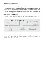
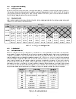


3
NOTE:
All dimensions are in inches. For further A31 enclosure information, see the outline drawings online at
http://www.lamarchemfg.com/info/enclosure-drawings.html
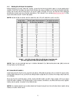
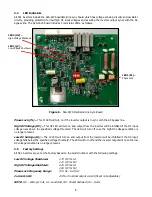
2.1.1 Rack-Mounting the A31
The A31 can be installed in most relay racks with standard EIA hole spacing. If a relay rack is needed, they are
available for purchase from La Marche. The
9D, 9E, 33, and 39
enclosures are shipped from the factory with
the necessary brackets installed for rear mounting on a relay rack
.
The rack mounting bracket for the
39
enclosure
allows
for mounting on a 19” or 23” rack,
and the
9D, 9E, and 33
enclosures allow
for mounting on a 23” rack.
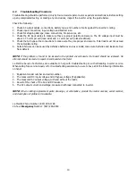
Rack Mounting Procedure
Before installing the inverter on the rack, locate the conduit entrances and assure the knockouts on the top,
sides, or bottom of the inverter are accessible after the inverter is rack mounted. Provide at minimum 6in (152mm)
of air space above and below to allow for cooling.
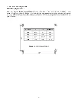
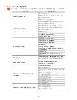
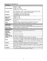
Figure 1 -
39 Enclosure Bolt Pattern
Figure 3
–
9D/9E Enclosure Bolt Pattern
Figure 2 -
33 Enclosure Bolt Pattern
10.438


