7
For Standard Inverters (No Static Switch):
1.
Push and hold the Pre-Charge button until the green READY LED illuminates.
*
2.
Release the Pre-Charge button and immediately turn on the DC breaker, then turn the inverter ON/OFF switch
(SW-1) to the
ON
position. The inverter should begin to emit a humming sound.
3.
Turn on the AC breaker.
4.
Measure the output voltage of the inverter across the AC LOAD terminals to assure that it agrees with
nameplate.
For Inverters with 1ms Static Switch (Option 22P/22S):
1.
Push and hold the Pre-Charge button until the green READY LED illuminates.
*
2.
Release the Pre-Charge button and immediately turn on the DC breaker, then turn the inverter ON/OFF switch
(SW-1) to the
ON
position. The inverter should begin to emit a humming sound.
3.
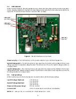
Turn on the AC breaker. The front panel LEDs will perform a lamp test. After the lamp test, the Inverter
Available LED should be lit. For option 22P, the Preferred Source LED should also be lit. For option 22S, the
Alternate Source LED should also be lit.
4.
Turn on the AC bypass source (utility). After a couple of seconds, and the Phase Lock and Utility Available
LEDs should additionally be on. Assure the inverter is set to Auto Retransfer by setting the Retransfer toggle
switch to Auto. For inverters with Option 22D, please read the appropriate instruction manual. For option 22S,
the Preferred Source LED should also turn on and the Alternate Source LED turn off.
5.
Measure the output voltage of the inverter across the AC LOAD terminals to assure that it agrees with
nameplate.
For Inverters with 10-15ms Static Switch (Option 164/165):
1.
Push and hold the Pre-Charge button until the green READY LED illuminates. *
2.
Release the Pre-Charge button and immediately turn on the DC breaker, then turn the inverter ON/OFF switch
(SW-1) to the
ON
position. The inverter should begin to emit a humming sound.
Inverter Prime (Option 164):
A.
Turn on the AC breaker. The LOAD ON PRIME and PRIME AVAIL. LEDs should be lit on the 139A static
switch board. On the front panel, the green INVERTER AVAILABLE LED should be lit.
B.
Turn on the AC bypass source (utility). The yellow BYPASS AVAILABLE LED should additionally be lit.
C.
Measure the output voltage of the inverter across the AC LOAD terminals to assure that it agrees with
nameplate.
Inverter Standby (Option 165):
A.
Turn on the AC breaker. The LOAD ON PRIME and PRIME AVAIL. LEDs should be lit on the 139A static
switch board. On the front panel, the green INVERTER AVAILABLE and the red LOAD ON ALTERNATE
LED should be lit.
B.
Turn on the AC bypass source (utility). The yellow BYPASS AVAILABLE LED should additionally be lit. The
LOAD ON ALTERNATE LED should be off after a couple of seconds.
C.
Measure the output voltage of the inverter across the AC LOAD terminals to assure that it agrees with
nameplate.
CAUTION:
Before resetting the DC breaker, the pre-charge instructions must be followed before restarting the
inverter or damage to the inverter may occur.
*NOTE:
If the green READY LED does not light, check the type and number of cells of the battery to verify that
it is correct. If the red REVERSE POLARITY LED illuminates, the battery has not been installed correctly.
Disconnect the battery wires immediately or damage to the inverter may occur.


