background image


5

DETAILED SET-UP GUIDE 


I. 

BATTERY INSTALLATION (When one temperature sensor is being used) 


1. 

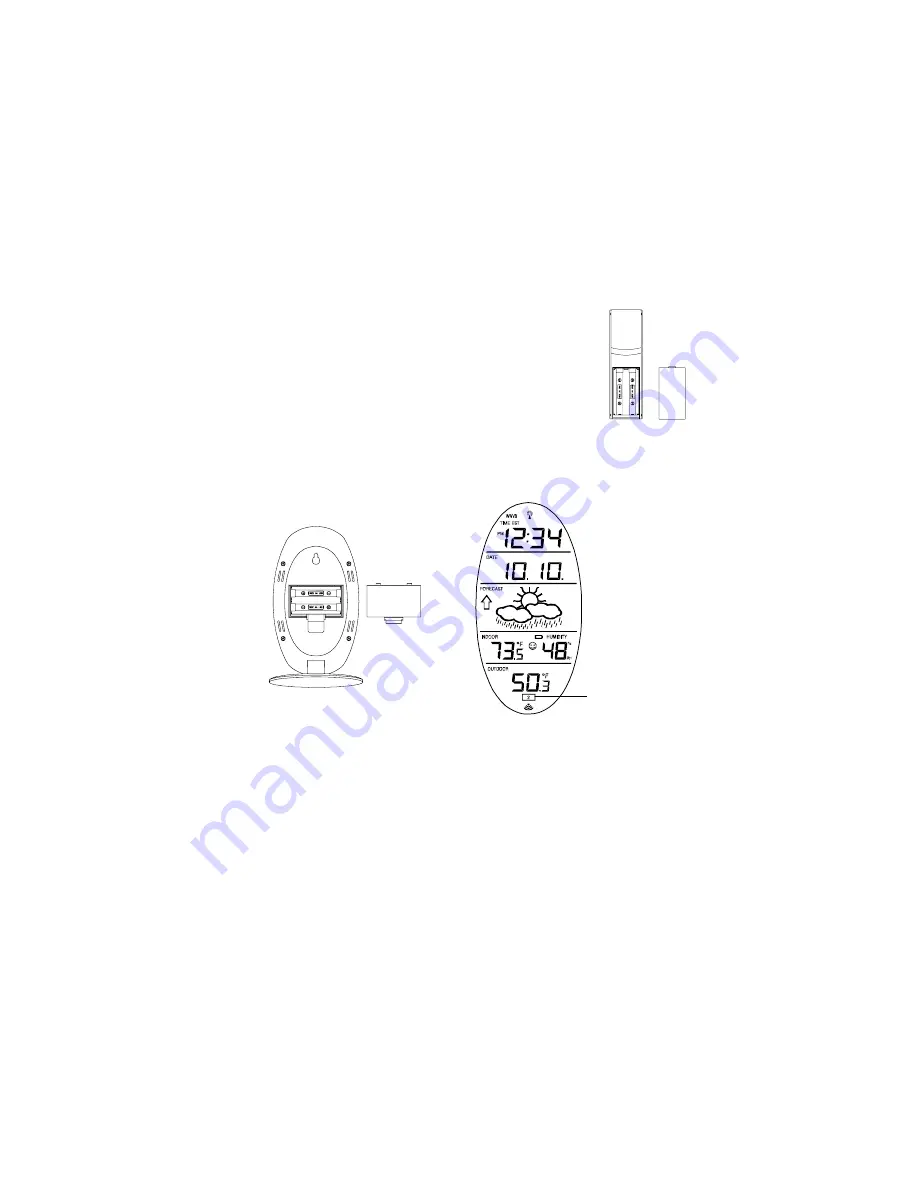
First, insert the batteries to the temperature sensor (see “

A. Remote Temperature 

Sensor

” below). 

2. 

Within 30 seconds of powering up the sensor, insert the batteries to the Weather 
Station (see “

B. 

Wireless Weather Station

” below). Once the batteries are in place, all 

segments of the LCD will light up briefly. Following the indoor temperature and 
humidity, and the time as 12:00 will be displayed. If they are not shown in LCD after 60 
seconds, remove the batteries and wait for at least 60 seconds before reinserting 
them. Once the indoor data is displayed user may proceed to the next step. 

3. 

After the batteries are inserted, the Weather Station will start receiving data signal 
from the sensor. The outdoor temperature should then be displayed on the Weather 
Station. If this does not happen after 2 minutes, the batteries will need to be removed 
from both units and reset from step 1 and the signal reception icon is no longer shown.


A.  REMOTE TEMPERATURE SENSOR 

1. 

Remove the mounting bracket.  The bracket snaps on 
and off easily. 

2. 

Remove the battery cover, by sliding the cover down. 

3. 

Observing the correct polarity install 2 AA batteries.  The 
batteries will fit tightly (to avoid start-up problems make 
sure they do not spring free). 

4. 

Replace the battery cover by sliding upwards. Be sure 
battery cover is on securely. 


B.  WIRELESS WEATHER STATION 

1. 

Remove the battery cover.  To do this, insert a solid object in the space provided 
at the lower-central position of the battery cover, then push up and pull out on the 
battery cover. 

2. 

Observe the correct polarity, and install 2 AA batteries. 

3. 

Replace the battery cover. 


*

 When the signal is successfully received by the Weather Station, the icon will be 

switched on. (If not successful, the icon will not be shown in LCD) So the user can 
easily see whether the last reception was successful (icon on) or not (icon off). On the 
other hand, the short blinking of the icon shows that a reception is being done now. 

Battery 
Cover 

Battery 
Cover 

Sensor signal  
reception icon

*


Summary of Contents for WS-9153TWC-IT

Page 1: ...WS 9153U IT Wireless 915 MHz Radio controlled Weather Station Instruction Manual...

Page 2: ...2 24 hour Time Setting 9 Setting the Time 10 11 Setting the Year Day and Month 11 Setting the Snooze 12 Setting the Temperature Format 12 Setting the Forecast Sensitivity 13 Features Weather Forecast...

Page 3: ...WWVB Radio Controlled Time The NIST National Institute of Standards and Technology Time and Frequency Division WWVB radio station is located in Ft Collins Colorado and transmits the exact time and da...

Page 4: ...Weather Station does not display both temperatures after the 15 minutes please retry the set up as stated above After both indoor and outdoor temperatures are displayed for 15 minutes you can place y...

Page 5: ...its and reset from step 1 and the signal reception icon is no longer shown A REMOTE TEMPERATURE SENSOR 1 Remove the mounting bracket The bracket snaps on and off easily 2 Remove the battery cover by s...

Page 6: ...setting If you do leave the program setting or want to program a specific setting follow each instructional step to program that setting I PROGRAMMING SEQUENCE AND DEFAULT SETTINGS The programming seq...

Page 7: ...e zone Note When a time zone for the U S is selected the corresponding abbreviation will appear above the time please see the table on the next page It is possible to select any time zone from 12 GMT...

Page 8: ...h 3 Press and release the SET button three times 4 RCC will appear in the date LCD and ON or OFF will flash in the time LCD 5 Press and release the IN button to select radio controlled time on or off...

Page 9: ...er a successful reception no more reception attempt would be made until the following day B MANUAL TIME SETTING Note When in the 12 hour format P M will appear to the left of the hour in the time LCD...

Page 10: ...button to select the temperature format 6 Press and release the SET button to confirm and advance to the forecast sensitivity setting XII SETTING THE FORECAST SENSITIVITY Note The forecast sensitivit...

Page 11: ...ssure readings to provide an accurate forecast creating a necessity to disregard all weather forecasting for 12 24 hours after the unit has been set up reset or moved from one altitude to another i e...

Page 12: ...pressure An arrow pointing up indicates that the air pressure is increasing and the weather is expected to improve or remain good an arrow pointing down indicates that the air pressure is decreasing a...

Page 13: ...ATURE RECORDS 1 Press the OUT button once MIN appears above the outdoor temperature and the LCD will flash indicating that the minimum temperature and the time and date of occurrence are displayed The...

Page 14: ...n 10 seconds of reception of the first sensor 6 The outdoor temperature from the second sensor and the channel 2 icon should then be displayed on the Weather Station If this does not happen after 2 mi...

Page 15: ...outside North facing wall The sending range is 330ft obstacles such as walls concrete and large metal objects can reduce the range Place both units in their desired location and wait approximately 15...

Page 16: ...forward 2 Fix a screw not included into the desired wall leaving approximately 3 16 of an inch 5mm extended from the wall 3 Place the Wireless Weather Station onto the screw using the hanging hole on...

Page 17: ...ends of a range making it harder to compare different ranges with different curves Under non laboratory conditions it is difficult to compensate for the above factors and obtain an accurate compariso...

Page 18: ...e Technology Ltd will pay all expenses for labor and materials for all repairs covered by this warranty If necessary repairs are not covered by this warranty or if a product is examined which is not i...

Page 19: ...1 Phone 608 782 1610 Fax 608 796 1020 e mail support lacrossetechnology com warranty work sales lacrossetechnology com information on other products web www lacrossetechnology com Questions Instructio...

Page 20: ...nd found to comply with the limits for a Class B digital device pursuant to Part 15 of the FCC Rules These limits are designed to provide reasonable protection against harmful interference in a reside...

Reviews: