background image


17

3.  Place all remote temperature sensor units in a numeric 

sequential order. 

4.  In sequential order, install batteries (follow the same battery 

installation procedures seen in section I. A) of the Detailed 
Set-Up Guide). 

5.  Install batteries into the indoor weather station. 
6.  Follow the Detailed Set-Up Guide for programming and 

operating instructions. 


B.  VIEWING AND OPERATING WITH MULTIPLE 
REMOTE TEMPERATURE SENSOR UNITS 
 

1.


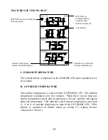
To view the temperature of a different remote temperature 
sensor unit, press and release the 

“CH”

 button.  A shift from 

one “boxed” number to the next should be observed in the 
OUTDOOR LCD.  

2.


To view the Minimum/Maximum temperature: first select 
which remote temperature sensor to read data from (indicated 
by the “boxed” number), then press and release the 

“MIN/MAX”

 button.  Pressing this button once will display 

the minimum temperature and the date and time the data was 
recorded.  Pressing this button a second time (while “MIN” is 
still displayed, otherwise press the button twice) will display 
the same data for the maximum recordings. 

3.


To reset the Minimum/Maximum readings, it is necessary to 
select which remote temperature sensor you wish to reset.  
Press and hold the 

“OUT”

 button for 5 seconds, the records 

for the selected remote temperature sensor unit will be reset. 


Summary of Contents for WS-9013U

Page 1: ...WS 9013U Wireless 433 MHz Radio controlled Weather Station Instruction Manual...

Page 2: ...light Saving Time Setting 9 10 Time Setting WWVB Manual 10 11 Setting Day Date and Year 11 12 Selecting F or C 12 Setting the LCD Contrast 13 Features Indoor Temperature 14 Outdoor Temperatures 14 Min...

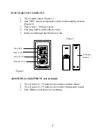
Page 3: ...ws 4 One strip double sided adhesive tape 5 Instruction Manual and Warranty Card ADDITIONAL EQUIPMENT not included 1 Two fresh AA 1 5V batteries for indoor weather station 2 Two fresh AA 1 5V batterie...

Page 4: ...ception is very limited during daylight hours The weather station will search for a signal every night when reception is best The WWVB radio station derives its signal from the NIST Atomic clock in Bo...

Page 5: ...e temperature sensor outdoors and set your time The remote temperature sensor should be placed in a dry shaded area The remote temperature sensor has a range of 80 feet Any walls that the signal will...

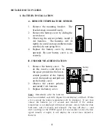
Page 6: ...vided at the lower central position of the battery cover then push up and pull out on the battery cover 2 Observe the correct polarity and install 2 AA batteries 3 Replace the battery cover Note Immed...

Page 7: ...step to program that setting I PROGRAMMING SEQUENCE The sequence for programming the indoor weather station and the default factory settings are 1 12 24 hour time setting 12 hour 2 Time Zone Zo 5 east...

Page 8: ...to toggle between 12 and 24 hour time 3 Press and release the SET button to confirm the 12 24 hour setting and to advance to Time Zone Setting III TIME ZONE SETTING The default time zone is EST Zo 5 E...

Page 9: ...ght Saving Time setting IV DAYLIGHT SAVING TIME DST SETTING 1 Press and hold the SET button for 3 seconds or until 12 h or 24 h flashes in the DATE LCD 2 Press and release the SET button 2 more times...

Page 10: ...overrides any manually set time The WWVB tower icon appearing in the TIME LCD will flash when a signal search is in progress will remain steady when the signal has been received and nothing will be di...

Page 11: ...reception at optimal times VI SETTING THE DAY DATE AND YEAR 1 Press and hold the SET button for 3 seconds or until 12 h or 24 h flashes in the DATE LCD 2 Press and release the SET button 5 more times...

Page 12: ...9 The default year will be flashing press and release the CH to select the appropriate year 10 Press and release the SET button to confirm and to advance to the F or C setting mode VII SELECTING F OR...

Page 13: ...The default setting Lcd 5 will flash in the DATE LCD 4 There are 8 LCD contrast levels to choose from Lcd 0 is the lightest and Lcd 7 is the darkest 5 Press and release the CH button to toggle through...

Page 14: ...temperature sensor unit in operation a boxed number will appear under the temperature This indicates which remote temperature sensor unit 1 2 or 3 is currently displaying its data in the OUTDOOR LCD...

Page 15: ...ess the IN button again to return to the current data display By waiting 20 seconds during either the minimum or the maximum readings the unit will automatically return to current data readings B VIEW...

Page 16: ...e extra remote temperature sensors can be purchased through the same dealer as this unit or by contacting La Crosse Technology directly A TX6U will monitor temperature only a TX3U will monitor tempera...

Page 17: ...e boxed number to the next should be observed in the OUTDOOR LCD 2 To view the Minimum Maximum temperature first select which remote temperature sensor to read data from indicated by the boxed number...

Page 18: ...permanently mounting to ensure that there is proper reception The indoor weather station should display a temperature in the OUTDOOR LCD within 4 minutes of setting up I THE REMOTE TEMPERATURE SENSOR...

Page 19: ...with the table stand or on the wall with the use of a wall hanging screw not included A USING THE TABLE STAND 1 The indoor temperature station comes with the table stand already mounted If you wish t...

Page 20: ...Solution 1 Set the LCD contrast to a higher number 2 Replace batteries Problem No outdoor temperature is displayed Solution 1 Remove all batteries reinsert into remote temperature sensor first then in...

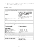
Page 21: ...ide this range Indoor temperature checking interval Every 10 seconds Outdoor temperature checking interval Remote Temperature Sensor Every 1 minute Outdoor temperature reception Indoor Weather Station...

Page 22: ...s examined which is not in need or repair you will be charged for the repairs or examination The owner must pay any shipping charges incurred in getting your La Crosse Technology Ltd product to a La C...

Page 23: ...nology com information on other products web www lacrossetechnology com FCC ID OMO 01RX receiver OMO 01TX sensor THIS DEVICE COMPLIES WITH PART 15 OF THE FCC RULES OPERATION IS SUBJECT TO THE FOLLOWIN...

Reviews: