background image


6

B. WEATHER 

STATION 

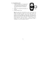
1.  Remove the battery cover.  To do this, insert 

a solid object in the space provided at the 
lower-central position of the battery cover, 
then push up and pull out on the battery 
cover. 

2.  Observe the correct polarity and install 2 AA 

batteries. 

Battery 
Cover 

3. 

Replace the battery cover.


Note:

  Immediately after the batteries have been installed, each LCD 

(Liquid Crystal Display) will flash and a tone will sound.  Within a few 
seconds the indoor temperature, indoor relative humidity and the 
weather icons (sun and clouds) will be displayed.  If not, then remove 
batteries for 10 seconds and reinstall. If the outdoor temperature is not 
displayed within four minutes, remove batteries from both units, wait 10 
seconds and reinstall.  The time will show -:-- and start searching for 
the signal. If it successfully receives the time signal (usually at night), it 
will display the correct time (default is Eastern). 


Summary of Contents for WS-7026U

Page 1: ...WS 7026U Wireless 433 MHz Radio Controlled Weather Station Instruction Manual...

Page 2: ...2...

Page 3: ...ay Date and Year 10 Selecting F or C 11 Setting the LCD Contrast 11 Features Back Light 12 Weather Forecast Icons 12 13 Indoor Temperature Humidity Comfort Level Indicator 14 Outdoor Temperature Humid...

Page 4: ...gy Time and Frequency Division WWVB radio station is located in Ft Collins Colorado and transmits the exact time signal continuously throughout the United States at 60 kHz The signal can be received u...

Page 5: ...eception time period of 12 00 AM to 6 00 AM 5 Mount the units ensuring that all units are sending and receiving signals Note The Thermo Hygro Transmitter transmits a signal every 3 minutes After the b...

Page 6: ...stalled each LCD Liquid Crystal Display will flash and a tone will sound Within a few seconds the indoor temperature indoor relative humidity and the weather icons sun and clouds will be displayed If...

Page 7: ...corresponding to the operation that you want to perform II 12 OR 24 HOUR TIME SETTING 1 Press and hold the SET button for 3 seconds or until 12 h flashes in the DATE LCD 2 Press the CH button to toggl...

Page 8: ...Time setting IV DAYLIGHT SAVING TIME DST SETTING 1 Press and hold the SET button for 3 seconds or until 12 h or 24 h flashes in the DATE LCD 2 Press the SET button 2 more times to reach the DST selec...

Page 9: ...is in progress will remain steady when the signal has been received and nothing will be displayed in all other situations If the WWVB time has not been received after 10 minutes of battery installatio...

Page 10: ...e automatically set once the WWVB signal is received However the day date and year can be manually set and will flash respectively in the DATE LCD during manual programming 3 The weekday will be flash...

Page 11: ...II SETTING THE LCD CONTRAST 1 Press and hold the SET button for 3 seconds or until 12h or 24h flashes in the DATE LCD 2 Press the SET button 10 more times to reach the LCD contrast setting mode 3 The...

Page 12: ...automatically shutting off II WEATHER FORECAST The weather forecasting feature is estimated to be 75 accurate The weather forecast is based solely upon the change of air pressure over time The WS 702...

Page 13: ...irectly to rainy although it is possible for the change to occur quickly If the symbols do not change then the weather has not changed or the change has been slow and gradual B WEATHER TENDENCY ARROWS...

Page 14: ...ture is explained in further detail in section VI Adding Outdoor Thermo Hygro Transmitters V MINIMUM AND MAXIMUM TEMPERATURE RECORDS The WS 7026U keeps a record of the MINIMUM and MAXIMUM temperature...

Page 15: ...d date of occurrence are displayed 3 While MAX is still displayed press the OUT button again to return to the current data display Or you can wait 20 seconds during either the minimum or the maximum r...

Page 16: ...directions above for alarm 1 using the AL2 button instead of the AL1 button The 2 icon will represent activation and deactivation of alarm 2 B SNOOZING AND STOPPING THE ALARM 1 The snooze function is...

Page 17: ...overs to all Remote Transmitter units 3 Place all Remote Transmitter units in a numeric sequential order 4 In sequential order install batteries follow the same battery installation procedures seen in...

Page 18: ...taining reliable data To achieve a true temperature reading avoid mounting where direct sunlight can reach the Thermo Hygro Transmitter We recommend that you mount the Thermo Hygro Transmitter on a No...

Page 19: ...d The mounting surface should be smooth and flat 2 Remove the protective strip from one side of the tape Press firmly onto the designated area on the back of the mounting bracket 3 Remove the protecti...

Page 20: ...priate location B WALL MOUNTING 1 Remove the table stand To do this pull down on the stand from the rear and rotate forward 2 Fix a screw not included into the desired wall leaving approximately 3 16...

Page 21: ...4 If there are still problems contact La Crosse Technology Problem Hour is incorrect minute and date are correct Solution Be sure correct time zone and daylight saving time are selected Problem The L...

Page 22: ...displays and units with a soft damp cloth Do not use solvents or scouring agents They may mark the displays and casings Do not submerge in water Immediately remove all low powered batteries to avoid l...

Page 23: ...interval Every 10 seconds Indoor Humidity checking interval Every 1 minute Outdoor Temperature and Humidity checking interval Thermo Hygro Transmitter Every 1 minute Outdoor Temperature and humidity...

Page 24: ...OGY WILL NOT ASSUME LIABILITY FOR INCIDENTAL CONSEQUENTIAL PUNITIVE OR OTHER SIMILAR DAMAGES ASSOCIATED WITH THE OPERATION OR MALFUNCTION OF THIS WEATHER STATION THIS PRODUCT IS NOT TO BE USED FOR MED...

Page 25: ...VICE COMPLIES WITH PART 15 OF THE FCC RULES OPERATION IS SUBJECT TO THE FOLLOWING TWO CONDITIONS 1 THIS DEVICE MAY NOT CAUSE HARMFUL INTERFERENCE AND 2 THIS DEVICE MUST ACCEPT INTERFERENCE RECEIVED IN...

Reviews: