


Marine Systems
Aviation Recorders
Page 3–12
Initial Issue
165M0601-00
Feb. 01/05
6
4
9
1
3
7
8
2
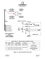
J1 Pilot Port Connector
72 in.
2
1.8 m
0.05 m
5
P2 DB9 Connector
Figure 3–4. Pilot Port Cable
NOTE:
A Digital Volt Meter may be used to determine the “A” and “B” polarities. A
negative voltage when referenced to ground would indicate “A”, while a positive
voltage when referenced to ground would indicate “B”.
Table 3–3. Pilot Port Pinout
J1 Pin
Name
Description
Pair Color P2 Pin
1
PILOT_TXA
RS4–22 Compliant Output A
Blue
2
2
GND
Signal/Power 0 Volt Reference
Black
5
3
+ 8V
+ 8.0 Volt (
5%) Output Used to Power External
Test Equipment. External Equipment should be
Current Limited to 300mA
4
PILOT_TXB
RS–422 Compliant Output B
Black
7
5
PILOT_RXA
RS–422 Compliant Input A
Green
8
6
PILOT_RXB
RS–422 Compliant Input B
Black
3
7
TRACE/BOOT_TX
TTL–Level RS–232 Serial Output (Trace Message/
Bootload Output)
8
RX_SINAD
TDMA / DSC FM Discriminator Output used to
Test Receiver Performance during Special Test
Modes.
9
NO CONNECT
Not Used


