background image

13

IGNITER AND ELECTRODE

Servicing of the igniter and electrode is needed when a
spark at the electrode is not seen.  This may happen with
hard use over a long period of time, or due to dust or dirt
accumulation.

If you do not see a spark being generated at the electrode
check the following areas:

A. Igniter

1.

Pull the wire from the push button igniter.

2.

Place a metal object, (such as a screwdriver tip)
about 1/8 in. from igniter.

3.

Push the igniter’s button several times.  If spark is not
seen, replace igniter.

B. Electrode

1.

Ensure the wire between the electrode and the igniter
is properly connected.  All connections should be
good and tight.

2.

Check the wire for nicks, cuts, or mars.  Nicks or cuts
will prevent a spark from being generated at the
electrode tip.  Replace the electrode if necessary.
The electrode ships with the wire.
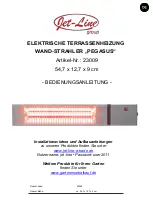
3.

Ensure the electrode tip is not out of position and is
not corroded.  The tip should be located at the
midpoint of the pilot orifice and positioned so it
sparks across to the outside edge of the pilot orifice.
See Fig. 3.

4.

Verify that the electrode’s ceramic body is not
cracked and that the electrode tip does not move
within its insulative body.  If it does, replace the
electrode.

BURNER ORIFICE

ATTENTION

Use only a soft brush, dry rag, or compressed air to
clean the burner orifice.

Do not push instruments into the orifice holes.  As the
holes are drilled at a specific angle and diameter.

Doing so may distort or enlarge the holes, creating
improper combustion and burner flames extending
beyond the heater’s case barrel.
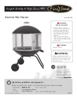
1.

In replacing the burner orifice, make sure the orifice
body and its holes are positioned properly.  See Fig. 4
representing top view of burner.  If the orifice body is
not positioned properly, the burner flame will not be
directed within the heater and improper combustion
may occur.

2.

The basic steps used in removal of the burner orifice
are the same as those used in removal of the pilot
orifice.

Fig. 4

ELECTRODE

BURNER

BURNER ORIFICE

Summary of Contents for Workman 100 Plus

Page 1: ...tested and evaluated by C S A International in accordance with Standard ANSI Z83 7 CSA 2 14 and is listed and approved as a direct fired vertical convection construction heater for use on combustible...

Page 2: ...property damage personal injury or loss of life GENERAL HAZARD WARNING Failure to comply with the precautions and instructions provided with this heater can result in Death Serious bodily injury or b...

Page 3: ...ert training and knowledge of gas heaters and should not be attempted by anyone who is not so qualified See page 6 for definition of the necessary qualifications Contact your local L B White distribut...

Page 4: ...sions Inches L x W x H Minimum Safe Distances From Nearest Combustible Materials Fuel Consumption Per Hour Inlet Gas Supply Pressure Acceptable at the Inlet of the Heater for Purpose of Input Adjustme...

Page 5: ...29 CFR 1926 154 Temporary Heating Device ANSI A10 10 Safety Requirements for Temporary and Portable Space Heating Devices or the Natural Gas and Propane Installation Code CAN CSA B149 1 as appropriat...

Page 6: ...ions about applications 4 Other standards govern the use of fuel gases and heat producing products in specific applications Your local authority can advise you about these 5 Use only compressed air so...

Page 7: ...s involved for cleanliness and proper application of pipe compound before further tightening Furthermore tighten the gas connections as necessary to stop the leak After all connections are checked and...

Page 8: ...ion of the heater Do not use the heater in a propane gas system or application If you are in doubt contact the L B White Co Inc 12 Take time to understand how to operate and maintain the heater by usi...

Page 9: ...0 seconds to allow the thermocouple to warmup so the pilot stays lit after the pilot knob is released 5 When pilot remains lit position knob to on Main burner will light WARNING Burn Hazard Close the...

Page 10: ...ngs are available at no cost 1 Before cleaning shut off all gas supply valves 2 The heater should have dirt or dust removed periodically a Before each use give the heater a general cleaning using comp...

Page 11: ...on See Fig 2 5 Open fuel supply valve to heater C READING PRESSURES 1 Light the pilot and start the heater 2 With heater operating the pressure gauges should read the pressures specified on the datapl...

Page 12: ...he pilot orifice Do not use a pliers to remove the pilot orifice from its gas supply line Doing so may round off the hex sides of the orifice making for difficult servicing later on Always use a wrenc...

Page 13: ...rroded The tip should be located at the midpoint of the pilot orifice and positioned so it sparks across to the outside edge of the pilot orifice See Fig 3 4 Verify that the electrode s ceramic body i...

Page 14: ...released Insufficient time allowed for pilot Hold in pilot button for 30 seconds to allow proper light to heat up thermocouple warm up Loose thermocouple Tighten thermocouple at gas control and make s...

Page 15: ...all metering device used to supply gas for the dual purpose of igniting the main burner and heating the thermocouple Works directly in conjunction with the thermocouple PILOT SAFETY GAS CONTROL VALVE...

Page 16: ...Parts Identification Parts Schematic 16 1 2 8 9 4 6 3 7 5 15 18 14 16 13 17 12 10 11 19...

Page 17: ...t 570434 5 Spacer 22298 6 Tube Pilot w Nuts and Sleeves 571515 7 Ell 3 8 in 01175 8 Bushing 01544 9 Thermocouple 571030 10 Orifice Pilot 22260 11 Head Pilot 571557 12 Bracket 571022 13 Nipple 5 in 808...

Page 18: ...nths of the date code marked on the part If the defect occurs more than 24 months later than the date code but within 24 months from the date of purchase by the end user a copy of a bill of sale will...

Reviews: