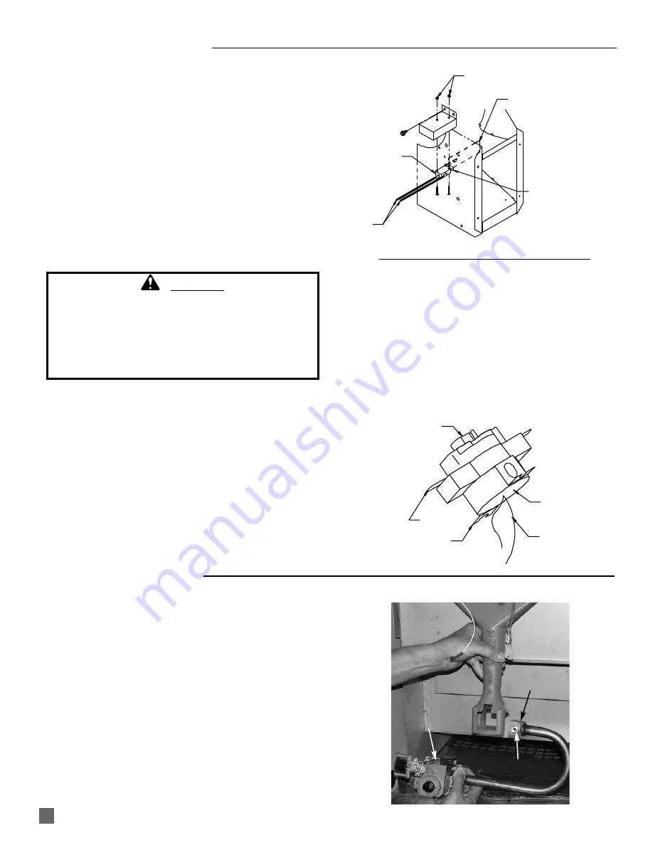
background image

17

AIR PROVING SWITCH

SWITCH W/ PADDLE

LEADS

NUTS

PADDLE

OBLONG HOLE

HOUSING SIDE
      PANEL

1.

Remove two sheet metal screws holding air proving
switch blower housing.  Remove assembly by turning
switch assembly 90 degrees so the switch paddle
can be pulled through oblong hole on side of fan
housing.  See Fig. 13.

3.

Disconnect the leads from the air proving switch.

4.

When installing replacement switch, use care in not
bending the switch arm, otherwise ignition problems
may occur.

FIG. 13

The high limit switch should be tested a minimum of once
per year when the heater is given a thorough cleaning.

1.

Re m ove   t h e   h i g h   l i m i t   s w i t c h   f ro m   t h e   h e a t
chamber.

2.

Holding the switch by one of its mounting legs or
electrical terminals, apply a small flame only to the
sensing surface on the back of the switch.  Be
careful not to melt the plastic housing of the switch
when conducting this test.

3.

Within a minute, you should hear a pop coming
from the switch, which indicates the contacts of the
switch have opened.

4.

Allow the switch cool down for about a minute
before firmly pressing the red reset button on the
switch.

5.

Check for electrical continuity across the switch
terminals to make sure the contacts have closed.

6.

Reinstall the switch back into the heater.  

FIG. 14

TESTING THE MANUAL RESET HIGH LIMIT SWITCH

RESET BUTTON

SENSING
SURFACE

TERMINAL

FLAME

MOUNTING
LEG

WARNING

Fire Hazard

Do not operate the heater with the high limit switch
bypassed.  

Operating the heater with a bypassed high limit switch
may lead to overheating, possibly resulting in a fire,
with subsequent damage to the heater, building
damage, or loss of livestock.

GAS CONTROL VALVE

1.

Remove the following

-- Hose and sediment trap from inlet of gas valve
-- Screws securing valve bracket to heater base. 
-- Burner bolt from underside of base.
-- Screws and spacers securing burner casting to 

heat chamber.

2.

Remove control valve with burner from heater. Pivot
the valve/manifold assembly as necessary so orifice
block on manifold clears the burner casting venturi
port..

3.

Replace components as needed.

FIG. 15

ORIFICE
BLOCK

GAS CONTROL
VALVE

BURNER
ORIFICE

Summary of Contents for Therma Grow HW220

Page 1: ...row Greenhouse Heaters View this manual online at www lbwhite com ATTENTION ALL USERS This heater has been tested and evaluated by C S A International in accordance with Canadian Gas Association Stand...

Page 2: ......

Page 3: ...ents paint thinner dust particles or unknown chemicals Failure to follow these instructions may result in a fire or explosion Fire or explosions can lead to property damage personal injury or loss of...

Page 4: ...y questions about the use of the equipment or its application The L B White Co Inc has a policy of continuous product improvement It reserves the right to change specifications and design without noti...

Page 5: ...cally operated and electrically interlocked with the heater to prevent heater operation if air inlet and exhaust outlet do not open when heating is required Model Indoor Mounting Air Exchange Requirem...

Page 6: ...fore you return Properly trained service people must repair the leak check for further leakages and then relight the appliance for you WARNING Do not use this heater for heating human living quarters...

Page 7: ...te this heater with any safety device that has been bypassed Do not operate this heater unless all of these features are fully functioning 6 Do not operate the heater with its door open or panel remov...

Page 8: ...range specified on the dataplate at all times Contact your gas supplier or the L B White Co Inc if you have any questions 5 The heater s gas regulator with pressure relief valve should be installed ou...

Page 9: ...ure you know how to shut off the gas supply to the building and also to the individual heater Contact your fuel gas supplier if you have any questions 17 Any defects found in performing any of the ser...

Page 10: ...rovided in the duct kit Ensure the motorized air inlet and the heater s air inlet are kept free of any blockages FIG 4a Blower Outlet View FIG 4c Side View FIG 4d Alternate Air Inlet Locations ENG BYN...

Page 11: ...IG 6 2 Assemble eyebolts and chain according to the illustration and tighten all eyebolts securely FIG 7 3 Ensure the heater is securely fastened to overhead supports and is hanging level Check crossw...

Page 12: ...ent position the heater fan operates continuously In the vent mode the heater then supplements or provides air circulation within the greenhouse This heat vent capability can be controlled by a buildi...

Page 13: ...GREEN BROWN BROWN YELLOW YELLOW GAS CONTROL VALVE GROUND RED BLACK WHITE GREEN HI LO C BUILDING CONTROLLER HEAT CONTACT TO CONTROL FROM CONTROL LEAVE WIRE NUT ON LEAD HIGH LIMIT SWITCH GAS CONTROL VAL...

Page 14: ...s view is to show general assembly of the components only The regulator must always be mounted so its vent regardless of location on the regulator is always pointed downward 3 Tighten all connections...

Page 15: ...art again and shortly thereafter ignition will occur NOTE It is normal for air to be trapped in the gas hose on new installations The heater may attempt more than one trial for ignition before the air...

Page 16: ...ther flammable vapors and liquids 2 Have your gas supplier check all gas piping annually for leaks or restrictions in gas lines 3 Regulators must be periodically inspected to make sure the regulator v...

Page 17: ...air or a soft dry rag Do not use files drills broaches etc to clean the orifice Doing so may enlarge the hole causing combustion or ignition problems Replace the orifice if it cannot be cleaned proper...

Page 18: ...icates the contacts of the switch have opened 4 Allow the switch cool down for about a minute before firmly pressing the red reset button on the switch 5 Check for electrical continuity across the swi...

Page 19: ...e inlet pressure is correct but the burner manifold pressure does not agree with that specified on the dataplate then the HI and LO heat output feature of the gas control valve requires adjustment 5 T...

Page 20: ...d shield 3 Ensure the igniter is located so the its lip on back side of igniter is resting on the edge of the mounting bracket and the mounting hole in the igniter aligns with the mounting hole in the...

Page 21: ...ermostat Thermostat closes and returns 24 volts to terminal W on ignition control Red light on ignition control is illuminated Ignition control sends flame sense current to flame sensor Ignition contr...

Page 22: ...ed to power supply Check breakers Is proper voltage delivered to selector switch Check all wiring for defects Repair or repalce if needed Yes Does selector switch send voltage to the transformer Check...

Page 23: ...f ignition is not achieved after the third trial the heater will lock out and the ignition control module will present the three time flash pattern Either recycle the heater or wait for heater to atte...

Page 24: ...sary No Is fan wheel plugged with dirt Is there an obstruction in blower outlet preventing air proving switch closure No Are 115 volts sent from ignition control terminal IND to motor relay No If impr...

Page 25: ...e and component Repair or replace as necessary or replace ignition control Provide proper pressure to heater and check with a gauge Check for voltage to switch Check wiring and repair if defective If...

Page 26: ...mbly and housing Repair or replace as necessary Yes Reconnect wires to capacitor Defective capacitor Replace the motor No Yes Are wires disconnected from capacitor No Five Times Rapid On Off cycling o...

Page 27: ...26 Electrical Connection and Ladder Diagram 115 Volt Supply...

Page 28: ...27 230 Volt Supply TRANSFORMER 24 VOLT 120 VOLT...

Page 29: ...box within the appliance that provides an area where burner flame mixes with combustion air thereby providing heat High Limit Switch Safety device wired into the control system which is used to break...

Page 30: ...Parts Identification PARTS SCHEMATIC 29 39 40 41 26 38 25 21 29 27 31 37 36 35 34 33 14 13 15 18 20 19 16 17 6 7 8 9 10 11 12 4 3 2 1 5 28 24 23 22 32 30...

Page 31: ...9 19 Flame Sensor 520139 20 High Limit Switch LP Gas 572501 Natural Gas 505566 21 Heat Chamber LP Gas 572499 Natural Gas 572500 22 Boot Selector Switch 571939 23 Selector Switch w Boot 571906 24 Contr...

Page 32: ...of the equipment and in any event L B White s liability in connection with the equipment including for claims based on negligence or strict liability is limited to the purchase price Some states do no...

Reviews: