background image

Inspection and preventive maintenance

Listening test

enclosure

preset

usable bandwidth

SB6i

[SB6_100]

29 Hz - 150 Hz

Procedure

1.

Load the preset on an LA2Xi / LA4X / LA7.16i / LA12X amplied controller.

2.

Connect a sinus generator to the amplied controller.

Risk of hearing damage

Set a low sound level to start and use ear protection to adjust before testing.

3.

Scan the bandwidth focusing on the usable range.

The sound should remain pure and free of unwanted noise.

4.

Focus on the 25 Hz frequency.

The sound should remain pure and free of unwanted noise.

Troubleshooting for LF speakers

One or more LF speaker produces distorted, buzzing, rubbing, clicking, mufed or weak sound.

Possible causes

• The screws are not tightened with the appropriate torque.
• There is an air leak in the gasket.
• There is dust on the cone.
• The cone is damaged.
• The surround is torn or delaminated.
• The voice coil or the spider is damaged.

Procedure

1.

Perform the speaker disassembly procedure.

2.

Visually inspect the cables and the connectors.

3.

Visually inspect the speaker cone, the voice coil and the spider.
If any damage is visible, replace the speaker.

4.

Carefully clean the speaker with a dry cloth.

5.

Perform the reassembly procedure.
Replace the speaker gasket and the screws.
Apply the recommended torque.

6.

Repeat the listening test.
If the problem persists, replace the speaker.

Troubleshooting for installation enclosures

One or more enclosure produces a high-pitched, leaking air sound.

Possible cause

• Placeholder screws are missing.

Procedure

Visually inspect the screws on both sides of the enclosures.
Secure placeholder screws in the empty inserts.

20 

 SB6i owner's manual (EN) version 1.0

Summary of Contents for SB6i

Page 1: ...SB6i owner s manual EN ...

Page 2: ...anual EN version 1 0 Distribution date November 25 2022 2022 L Acoustics All rights reserved No part of this publication may be reproduced or transmitted in any form or by any means without the express written consent of the publisher ...

Page 3: ...l safety 13 Loudspeaker con gurations 14 SB6i in standard con guration 14 Inspection and preventive maintenance 15 How to do preventive maintenance 15 Rigging part inspection 16 Mechanical system overview 16 Acoustical check 18 Rigging procedures 21 Tools 21 Wall or ceiling mounting SB6i with SB6i onCW 21 Connection to LA ampli ed controllers 25 Cabling schemes for SB6i 25 Cabling SB6i 27 Correcti...

Page 4: ...D R Trapdoor 32 D R LF speaker 33 Speci cations 34 SB6i 34 SB6i onCW 35 APPENDIX A Recommendation for speaker cables 36 APPENDIX B Speci cations for custom rigging 37 4 ...

Page 5: ...he rigging techniques and safety recommendations outlined in this manual Ensure personnel health and safety During installation and set up personnel must wear protective headgear and footwear at all times Under no circumstances is personnel allowed to climb on a loudspeaker assembly Respect the Working Load Limit WLL of third party equipment L Acoustics is not responsible for any rigging equipment...

Page 6: ...r notice Check www l acoustics com on a regular basis to download the latest document and software updates Long term exposure to extreme conditions may damage the product For more information refer to the Products weather protection document available on the website Read the maintenance section of this document before servicing the product Contact L Acoustics for advanced maintenance Any unauthori...

Page 7: ...6i owner s manual is intended for all actors involved in the system design implementation preventive and corrective maintenance of the SB6i system It must be used as follows 1 Read the technical description for an overview of all system elements their features and their compatibilities Electro acoustical description p 10 Rigging system description p 11 2 Prepare the system con guration Consider th...

Page 8: ... SB6i Ultra shallow subwoofer 2 6 5 Powering and driving system LA2Xi LA4X LA7 16i LA12X Ampli ed controller with DSP preset library and networking capabilities Refer to the LA2Xi LA4X LA7 16i LA12X owner s manual for operating instructions Cables 2 2 5 mm cable speaker cable with bare wire endings Adapt the cable length to the installation custom 2 point speakON cable 2 point speakON cable 2 5 mm...

Page 9: ... for remote control and monitoring of ampli ed controllers Refer to the Soundvision help Refer to the LA Network Manager help System component illustrations Cables 2 2 5 mm cable custom 2 point speakON cable Rigging accessories SB6i onCW Software applications Soundvision LA Network Manager SB6i owner s manual EN version 1 0 9 ...

Page 10: ...elay polarity mute OUT 1 SB IN A 0 dB 0 ms ON OUT 2 SB IN A 0 dB 0 ms ON OUT 3 SB IN A 0 dB 0 ms ON OUT 4 SB IN A 0 dB 0 ms ON Connectors IN LINK SB6i 1 4 point terminal block with push in connection Internal pinout for L Acoustics subwoofers Terminal block points IN IN Transducer connectors LF LF 10 SB6i owner s manual EN version 1 0 ...

Page 11: ...ll or a ceiling using the inserts on the back to secure dedicated rigging accessories Risk of acoustic leaks Always put the placeholder screws back when the inserts are not used The logo on the front face can be rotated to adapt to every con guration SB6i owner s manual EN version 1 0 11 ...

Page 12: ... four silent blocks fasteners for assembly and safety M6x35 Torx x4 spacer x4 washer x8 optional surface mounting plate x2 silent block x4 safety screw x4 Fasteners for wall mounting or ceiling mounting Secure the rigging element with four round or pan head M6 screws Select screw length and anchors applicable to the wall or ceiling properties 12 SB6i owner s manual EN version 1 0 ...

Page 13: ...udio video information and communication technology equipment Part 1 Safety requirements The deployments described in this manual achieve a safety factor of 5 SB6i con guration rigging accessory safe maximum limit wall mounted ceiling mounted SB6i onCW 1 SB6i owner s manual EN version 1 0 13 ...

Page 14: ...tem with an upper frequency limit at 60 Hz 100 Hz and 200 Hz respectively in order to optimize the acoustic coupling with a main full range system The SB6i subwoofer is driven by the LA2Xi LA4X LA7 16i LA12X ampli ed controllers Preset SB6_60 SB6_100 SB6_200 Low frequency limit 10 dB 29 Hz 29 Hz 32 Hz Delay values When combining a line source with subwoofers delays may have to be added to the pres...

Page 15: ...ection p 16 on each rigging part Use the Mechanical system overview p 16 to identify critical parts of the system If any parts are damaged contact your L Acoustics representative for further instructions Acoustics Perform the Enclosure check p 18 Perform the Listening test p 20 to detect any degradation in sound quality If necessary refer to the Corrective maintenance p 30 section for speaker repa...

Page 16: ...nts holes missing safety cues missing identi cation labels missing or loose fasteners Replacing screws If a screw is loose remove and replace it Always use the new screws provided in the repair kit If no new screw is available add blue threadlocker before reusing the screw Do not apply more than the indicated torque 3 Check the geometry of the part to identify critical deformations What to do next...

Page 17: ...ection and preventive maintenance SB6i mounted on a wall or ceiling with SB6i onCW safety screws are tightened silent blocks are not loose mounting screws are not loose SB6i owner s manual EN version 1 0 17 ...

Page 18: ... Do not connect enclosures in parallel Ampli ed controllers LA4X must run at least rmware version 1 1 0 LA4X load sensors must be calibrated Refer to the Load Sensor Calibration Tool technical bulletin for more information LA4X must warm up for at least 10 minutes after power up Do not power off reboot or switch to standby mode to avoid resetting the countdown Load a preset corresponding to the co...

Page 19: ...tes are met in particular that the loaded preset corresponds to the connected speaker s family b inspect the cables and connections c go to step 8 p 19 8 Under NC NOK and UNDEF results press and hold the corresponding OUT key The ampli ed controller displays the tested frequencies information on the measured impedance OPEN for open circuit found in NC results SHORT for short circuit found in NOK r...

Page 20: ...ropriate torque There is an air leak in the gasket There is dust on the cone The cone is damaged The surround is torn or delaminated The voice coil or the spider is damaged Procedure 1 Perform the speaker disassembly procedure 2 Visually inspect the cables and the connectors 3 Visually inspect the speaker cone the voice coil and the spider If any damage is visible replace the speaker 4 Carefully c...

Page 21: ... SB6i with SB6i onCW wall mounting type of deployment ceiling mounting rigging accessories SB6i onCW including surface mounting plates 4 M6 35 Torx screws 4 silent blocks 4 spacers 8 washers additional material 4 compatible screws and anchors torque screwdriver T30 Torx bit tools T20 Torx bit min number of operators 1 Fasteners for wall mounting or ceiling mounting Secure the rigging element with ...

Page 22: ...0 mm 16 14 in 6 6 mm 0 26 in min 50 mm 2 in 46 mm 1 81 in Make sure to leave enough space between the wall or ceiling and the sides of the rigging element to access the security screws when the enclosure is mounted 2 Secure the surface mounting plate on the wall or on the ceiling using the four spacers The washers can be added behind the spacers if the wall or ceiling is not perfectly at 22 SB6i o...

Page 23: ...screws from the back of SB6i T30 4 Mount the silent blocks to SB6i with the four M6 35 Torx screws x4 T30 5 N m 5 Prepare the cabling Refer to Cabling SB6i p 27 6 Mount the assembly on the surface mounting plates SB6i owner s manual EN version 1 0 23 ...

Page 24: ...Rigging procedures 7 Slide towards the bottom of SB6i to secure the assembly 8 Tighten the four safety screws and make sure the assembly is stable T20 x4 24 SB6i owner s manual EN version 1 0 ...

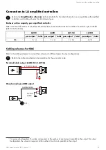
Page 25: ...6i LA12X per output total per output total per output total per output total SB6i 1 4 1 4 1 16 2 8 Cabling schemes for SB6i Refer to the cabling schemes to connect the enclosures to different types of output con gurations Refer to the cable manufacturer documentation for the wire color code Terminal block output LA2Xi SE LA7 16i 2 2 1 1 2 5 mm cables One channel speakON output 1 1 custom cable 2 5...

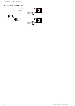
Page 26: ...Connection to LA ampli ed controllers Two channel speakON output 2 5 mm cable 1 1 2 5 mm cable 2 2 1 1 2 2 custom cable 26 SB6i owner s manual EN version 1 0 ...

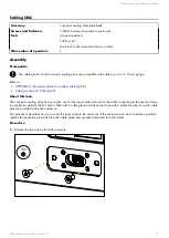
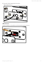
Page 27: ... Cabling schemes for SB6i p 25 About this task The connector sealing plate has two holes one for the input cable and one for the cable connecting to the next enclosure in parallel By default the rst hole is tted with a cable gland and the second one with a protective plug An extra cable gland is provided with each enclosure This procedure describes how to connect the input cable to the enclosure I...

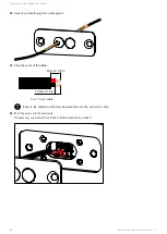
Page 28: ...3 Strip the wires of the cable 20 mm 0 8 in 10 mm 0 4 in 2 2 5 mm cable Refer to the cable manufacturer documentation for the wire color code 4 Push the wires into the terminals If necessary use a small tool in the hole the terminal to unlock it 28 SB6i owner s manual EN version 1 0 ...

Page 29: ...llers 5 Secure the connector sealing plate to the enclosure Apply a torque of 1 N m T30 1 N m What to do next To remove the cables use the small tool to unlock the terminals and pull on the wires SB6i owner s manual EN version 1 0 29 ...

Page 30: ...1 R 360NANO FACOM torque screwdriver 2 10 N m A 404 FACOM at plastic tool included in the L Acoustics Maintenance Toolcase Maintenance Toolcase The Maintenance Toolcase is a carry on suitcase that includes all the tools required to perform maintenance on L Acoustics products This toolcase is aimed at Certi ed Providers The Maintenance Toolcase uses a Peli 1510 Protector case that features three pr...

Page 31: ...d views In order to operate follow the order outlined here Each assembly refers to the corresponding Disassembly Reassembly D R procedure and the necessary repair kit Trapdoor LF speaker G03694 SB6i owner s manual EN version 1 0 31 ...

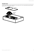
Page 32: ...R loudspeaker 6 SB6i 10 S100086 M5 16 Torx Prerequisite Place SB6i upside down on a at surface Exploded view For safety reasons always use the new screws and spare parts provided in the KR If no new screws are available use blue threadlocker Use a at plastic tool as a lever to remove the trapdoor x10 3 N m T25 32 SB6i owner s manual EN version 1 0 ...

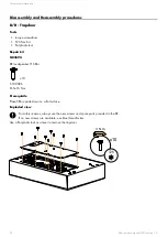
Page 33: ...hex Prerequisite Trapdoor removed See D R Trapdoor p 32 Exploded view For safety reasons always use the new screws and spare parts provided in the KR If no new screws are available use blue threadlocker Gradually tighten the screws following a star pattern x4 3 N m 4 mm What to do next Perform the Acoustical check p 18 procedures SB6i owner s manual EN version 1 0 33 ...

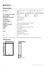
Page 34: ...mpedance 4 Ω Connectors 1 4 point terminal block with push in connection Rigging and handling 8 M6 inserts for rigging accessories Weight net 8 6 kg 18 lb Cabinet premium grade Baltic beech and birch plywood Front coated steel grill acoustically neutral 3D fabric Finish dark grey brown Pantone 426 C pure white RAL 9010 custom RAL code on special order IP IP55 1 Peak level at 1 m under half space c...

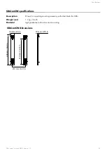
Page 35: ...ceiling mounting accessory with silent blocks for SB6i Weight net 1 1 kg 2 4 lb Material high grade steel with anti corrosion coating SB6i onCW dimensions 488 mm 19 2 in 58 mm 2 3 in 410 mm 16 14 in 210 mm 8 27 in 19 mm 0 75 in SB6i owner s manual EN version 1 0 35 ...

Page 36: ...w provides the recommended maximum length for loudspeaker cables depending on the cable gauge and on the impedance load connected to the ampli er recommended maximum length cable gauge 8 Ω load 4 Ω load 2 7 Ω load mm 2 SWG AWG m ft m ft m ft 2 5 15 13 30 100 15 50 10 33 4 13 11 50 160 25 80 17 53 6 11 9 74 240 37 120 25 80 Use the more detailed L Acoustics calculation tool to evaluate cable length...

Page 37: ...nce purposes L Acoustics accessories etc Grade of screws must be de ned by a quali ed person Take into consideration the number of inserts used weight and center of gravity of enclosure s and resulting action forces Prevent screws from loosening threadlocker spring washer SB6i has 12 threaded M6 inserts available for rigging Ultimate Tensile Strength 1160 N Ultimate Shear Strength 3300 N Recommend...

Page 38: ...Speci cations for custom rigging 38 mm 1 5 in 222 mm 8 74 in 489 4 mm 19 27 in 410 mm 16 14 in 210 mm 8 27 in 25 mm 0 98 in 39 7 mm 1 6 in 38 SB6i owner s manual EN version 1 0 ...

Page 39: ...L Acoustics 13 rue Levacher Cintrat 91460 Marcoussis France 33 1 69 63 69 63 info l acoustics com www l acoustics com ...

Reviews: