background image

Multi-Image Splicing Processor

17

Image Switch

Image 1

S1

Image 2

S1

Image 3

S1

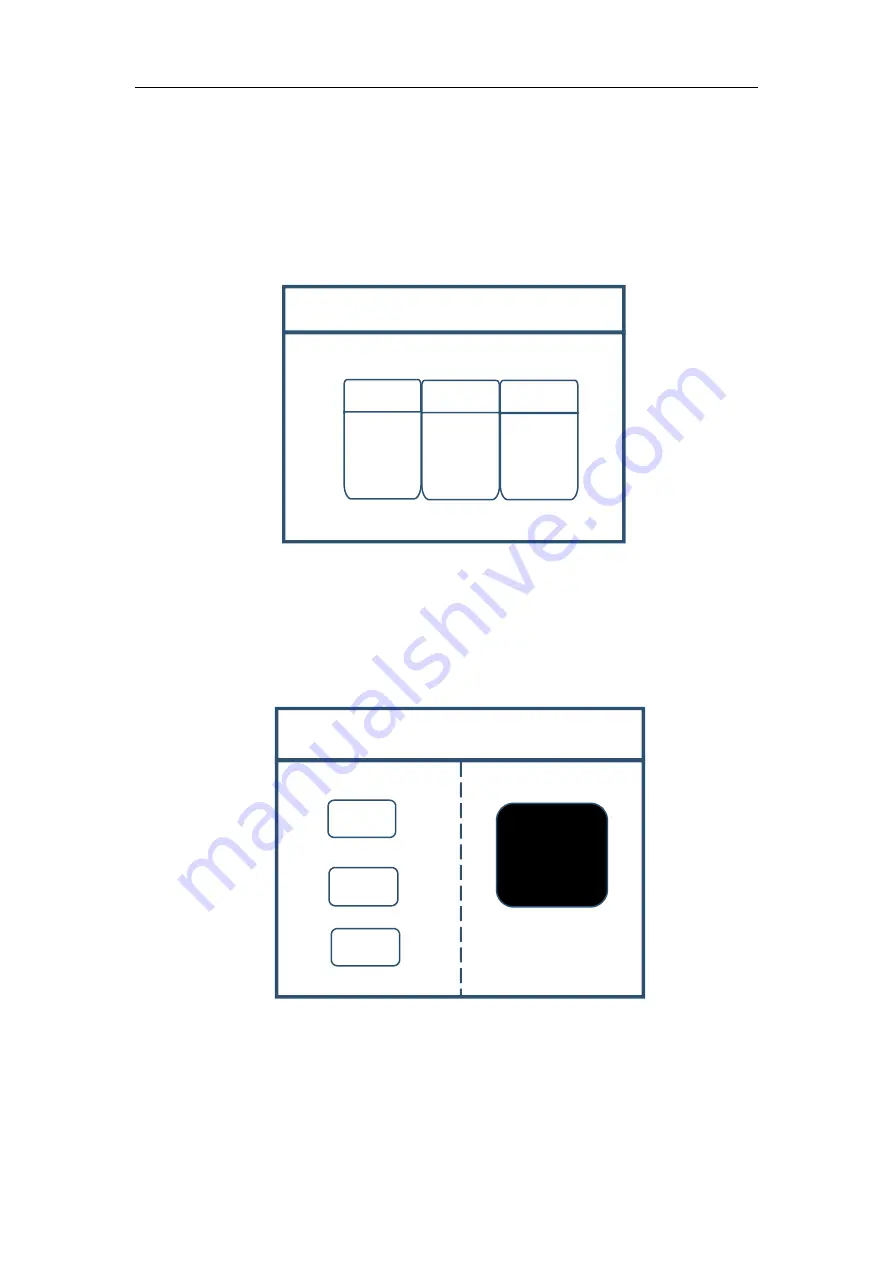
Output Condition Control

Black

Blue

Norma

Note:

Display

black

screen

WIN:

Image key. Click this key to enter into its interface and signal source

selection can be made in the following interface. Taking image 3 as instance, click
“WIN” to enter into image switch interface which shows current signal sources of
three images. If signal source switch is needed, rotate the knob first to select the
image and switch by “S1-S6” of the front panel.

OUT:

Output condition key. Click the key to enter into its interface with three

output options: blank screen, blue screen and normal screen. Selection of blank screen
means all output interfaces and large screen are blank; blue screen means all those are
blue; and normal screen refers to normal image output.

FUNC:

Function key. Click this key to enter into its interface. Common

functions include: brightness adjustment, special effect switch, VGA adjustment,
image matting setting, edge feather, transparency setting, intelligent warm backup,
preview monitor, IP setting, serial port, freeze frame, local and global, color space,
input brightness and switch time. The following are explanations of those common

Summary of Contents for U3

Page 1: ...Multi picture splicing processor Version v3 1 Release date February 2022 Manual Beijing KYSTAR Technology Co LTD Professional Ultra HD Video Display Control system integrated solution and service provider ...

Page 2: ...d affix legal liabilities of any infringement act Please read the manual carefully before using Any improper operation may cause damage to the product It is operated with electricity and sufficient attention should be attached Our company bears no responsibility for any property loss and personal injury incurred from any improper operation failing to follow the instructions in the manual If the pr...

Page 3: ...fter sales service personnel Ensure sound grounding For your safety please ensure that power cable is grounded soundly Keep away from strong magnetic field engine and transformer For normal operation of the device please keep it away from strong magnetic field enginer and transformer Guard against damp Keep operational environment dry If the equipment is inadvertently dampened do not power the dev...

Page 4: ...on 2 2 1 Front Pane 2 2 2 Back Panel 3 3 Device Debugging 4 3 1 Device Connection 4 3 2 Debugging Procedure 5 3 3 Case explanation 8 3 4 Function Key 15 3 5 Advanced Menu 20 4 Technical Parameters 21 5 FQAs 22 Appendix Graphics copy mode and extended mode setting 24 1 AMD Video Card 24 2 NVIDIA Video Card 24 ...

Page 5: ...nd SDI support 4K Ultra HD input and realize large screen point to point display 2 Support the output of 2 million 600 thousand pixel custom in copy mode in splicing mode the maximum level of 3840 pixels the vertical maximum 1920 pixel output 3 Support free form three image layout and realize central control of main screen side screen floor tile or canopy of the stage in an easy way 4 Support sign...

Page 6: ...irm debugging information 5 MENU MENU button you can enter the main MENU interface for device debugging 6 INFO information query button Example Query the real time status of input signals 7 WIN Screen information button Display screen signal source and switch screen signal source 8 S1 S6 Signal source button The input source behind the device is under the main menu screen and the parameter input s...

Page 7: ...ing card etc 4 LAN1 100m network control port It can debug the equipment through software when it is connected to the computer s 100 mbit s network port 5 AC 100 220V power interface It can be connected to ac power supply of 100 220V 6 INPUT S5 S6 extended INPUT Expandable with two conventional inputs or one 4KHDMI input 7 INPUT S1 S4 conventional INPUT Input interface includes one set of DVI one ...

Page 8: ...creen Control connection connect computer with device control port and debug device connection method There are three connection methods 1 Connect 100 mbit network control port with splicer LAN1 port which can set device software 2 Connect computer gigabit network port with splicer LAN2 port which can not only set device but also echo signal source image 3 Connect one crystal head of serial port l...

Page 9: ...osaic Note Copy Mode all output contents are consistent horizontal mosaic contents of all outputs are arranged horizontally vertical mosaic contents of all outputs are arranged vertically Step 2 select suitable splicing mode and click OK get back to main menu interface to select Screen parameter and enter into its setting interface Set loaded screen point of each output interface and click Confirm...

Page 10: ...to select Image layout and enter into image number selecting interface to select image number required to be set Note In case of signal image skip this step For multi image it s OK if image number and item requirements are in consistent Following operations can be taken when layouts are not consistent Step 4 Click OK and return to main menu interface select Image parameter and enter into its setti...

Page 11: ...ng of signal source image is required if horizontal size or vertical size is 0 it means no local extraction is required in this direction Step 6 Click MENU and return to main menu interface select Save setting to enter into Data storage interface select any mode and click OK to save data Note Mode 1 is default startup data of device boot it s suggested that the most common mode or that required by...

Page 12: ...onvenient when mode scenario is few 2 For User mode call of Main Menu click MENU and select User Mode to enter into its extraction interface Then select desired mode and click OK 3 3 Case explanation Device debugging steps are explained by following cases Case 1 screen size is 2112 896 and loading transmitting card is shown as picture below Requirement whole computer desktop should be displayed co...

Page 13: ...s two transmitting cards are in the 1x2 arrangement horizontal mosaics are needed then Step 2 Click OK to return to main menu interface select Large screen parameters to set size of each output interface Note Input according to corresponding transmitting card size of each output interface For OUT1 its horizontal size is 960 and vertical size 896 for OUT2 they are 1216 and 896 respectively Step 3 A...

Page 14: ...ata Click MENU to enter into main menu interface and then get into Save setting interface to select Mode 1 and click OK Things will be fine when it suggests saving successfully Note Mode 1 is default startup data of device boot it s suggested that the most common mode should be saved to Mode 1 and the device can save 32 kinds of modes at most Case 2 Screen size is 1792 1344 and loaded transmitting...

Page 15: ...ic Vertical Mosaic OUT1 Note All output interfaces OUT2 Display image 1 Display image 2 Debugging Procedure Step 1 Click MENU to enter into main menu interface Select Device mode and then Vertical Mosaic Note as two transmitting cards are in vertical arrangement horizontal mosaics are needed then Step 2 Click OK to return to main menu interface select Large screen parameters to set size of each ou...

Page 16: ...t of the back device just click S1 in the front which means choosing the signal to display on the screen Step 4 After selecting signal and normal display of large screen save all setting data Click MENU to enter into main menu interface and then get into Save setting interface to select Mode 1 and click OK Things will be fine when it suggests saving successfully Note Mode 1 is default startup data...

Page 17: ...n menu interface and select Image layout then Layout 3 Note Default layout of the device is three equal parts If it is desired there is no need to carry out step 6 If not the following operations are required Step 6 Click OK to return to main menu interface and select Image parameter to enter into its setting interface Set the following parameters Image Properties Horizontal Position Vertical Posi...

Page 18: ...ly 1344 and 0 and horizontal and vertical sizes are 448 and 1344 respectively Step 7 According to operation above screen body has been divided into three images with proportion of 1 2 1 Default display content of each image is S1 If different signal sources should be designated for each image click of front panel to enter into image switch interface Select image by rotate knob and choose signal by...

Page 19: ...combine the keys function and the LEDscreen display detailed introduces you to LED KS600 of menu system How to use the keys The front panel keys of LED KS600 Dare divided into four areas INPUTS FUNCTION MENU and NUMERIC besides them there is special numeric area including all the buttons of INPUTS and FUNCTION area INPUTS area In the default menu state press the button then could let the LED scree...

Page 20: ...y namely into set mode then anti clockwise knob can reduce the current parameter values Clockwise knob it can increase the current parameter values If you want to continue to set this paga other item please switch back to browse mode In navigation mode when user press the konb to adjust the data can be used as a step length switch key Numeric key area When browsing the menu if the current item par...

Page 21: ... front panel OUT Output condition key Click the key to enter into its interface with three output options blank screen blue screen and normal screen Selection of blank screen means all output interfaces and large screen are blank blue screen means all those are blue and normal screen refers to normal image output FUNC Function key Click this key to enter into its interface Common functions include...

Page 22: ...ent modes with the range of 0 2s 3s 4 VGA adjustment As VGA is analogue signal it tends to cause deviations among common functions The product has two kinds of VGA corrections which are automatic correction and manual correction 5 Image matting setting Image matting setting is to extract some caption or images and delete the rest parts which is often used in caption production Taking red caption a...

Page 23: ...with other parts unchanged 10 Color space Setting input signal source S1 and S2 for instance RGB YCbCr and other color spaces 11 IP setting Set device IP address mainly for software debugging 12 Local and global Switch local display or global display of any image on the condition that data of local display is already set 13 Freeze frame Set stillness or movement of any image which is often used fo...

Page 24: ...pports image text and caption overlay Hardware can be opened or closed with software setting 5 Scheduled Task Device can be switched in a regular time which can be used in unattended occasions For instance school screen can be switched to computer signal in 8 am to play motivational slogans and in 7 pm it can turn to STB signal to play CCTV news periodically 6 Multi machine cascade Device cascade ...

Page 25: ...mum of 1920 x 1200 60Hz EX 1 2 It is equipped with 2 channel DVI supporting DVI SDI HDMI1 3 1 4 CVBS and other signals Output port Type Quantity specification DVI D 2 The horizontal resolution is up to 3840 pixels The maximum vertical resolution is 1920 pixels DVI D 2 1 channel monitoring output 1 vessel out Control port Type Quantity specification RJ11 RS 232 1 The data transfer rate is 50 75 100...

Page 26: ...ion rapid display rate rich color and is widely applied among color displays Its signal source is normally desktop laptop VOD and Matrix CV Composite video signal also called composite video which can pack all signals together and transfer it as a whole Its signal source is normally camera DVD Cable Box VOD and video matrix Q2 Please give a brief introduction of the connection method of graphics s...

Page 27: ... connection or damage of the line Damage of COM drive of the board or serial port If suggestions above fail to solve your problems at last please contact our customer service in time We will help you to solve your problems as soon as possible Q6 What are the possible reasons for network overtime with network splicing processor A Possible reasons are as follows IP address of local connection is not...

Page 28: ...Card Right click on blank space of the desktop Property Setting Advanced enter into Graphics Drive Control Board Right click Copy Extended mode 2 NVIDIA Video Card Right click on blank space of the desktop Property Setting Advanced Enter into Graphics Drive Control Board Right click Copy Extended mode ...

Reviews: