background image


Full Color LED Video processor KS600 User Manual 

VI.Connection and installation 

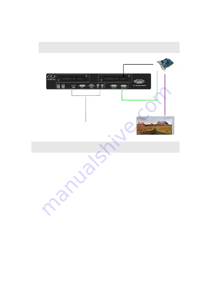
  Connection Diagram 


    Installation Procedure   


1.Make sure the led screen displays image normally when the graphics card controls 

sending card directly and the video processor is absent. 

2.

Make connection as above chart, connect DVI port of graphics card to the DVI-IN of   

the processor,then connect DVI-OUT of the processor to sending card.   

3.Power on the video processor after cables are connected accurately. 


Note: 

For the convenience of customers, the sending card can be loaded or unloaded in the 

processor, i.e. the sending card can be installed in the processor and powered by the processor, 

which can get rid of the shackles of desktop power supply. The installation method is as follows: 

① Remove the fixing corner of the sending card; 

② Loosen the knob on the rear panel, pull it out and remove the temporary baffle; 

③ A small four-wire plug is reserved in the processor. It corresponds to the wire groove in 

the sending card. Connect it and fix the sending card on the video processor; 

④ Reinstall and fix the drawer box, and connect the superimposed DVI interfaces. 


installation 

Signal source 

DVI cable   

N

et

w

o

rk


ca

b

le


LED screen 

Summary of Contents for KS600

Page 1: ...Full Color LED Video processor KS600 User Manual Full Color LED Video Processor KS600 User Manual Beijing KYSTAR Technology Co LTD ...

Page 2: ...for further use 2 Unplug the power plug when there is thunder and lightning or long time disuse 3 The device is not suitable for nonprofessionals please use under professionals instructions 3 Do not slip anything into the blowhole of the device in case of any damage or incident 4 Keep the device away from water or moisture environment 5 Keep the device away from cooling fin or other hot environmen...

Page 3: ...erview 5 II Product Features 6 III Technical Parameters 3 IV Work diagram 5 V Panel 6 Front 6 Back 7 VI Connection and installation 8 Connection diagram 8 Installation procedure 8 VII Device debug 9 Wizard mode 4 steps to achieve setup 9 VIII Control Menu 17 1 Language 18 ...

Page 4: ...User Manual 2 Factory settings 19 3 Technical support 19 4 Scheduled task 19 5 Transition effect 19 6 VGA setting 7 Contast setting 19 8 Image statics 19 9 Sound setting 19 10 Expert setting 19 IX FAQ Technical support and Contact Info 20 ...

Page 5: ... resolution will be reduced significantly when the signal format is converted 3 The control system of LED large screen can only capture and display the images of corresponding points on the LED large screen however in some sites the customer may need to display any size or the full computer desktop 4 With the shrinking of LED screen pitch and increasing of screen points the era that single picture...

Page 6: ...nce image display effect 5 Picture zoom in out freely adjust picture pixel by pixel the minimum size can be 1 pixel 6 Motion compensation avoid trailing of pictures 7 Noise reduction reduce noise stain 8 6 channel HD video signal inputs 2 channel video outputs 9 Max input resolution is 1920 1080 max output user defined resolution is 1920 1200 10 Key lock function prevent misoperation after debug 1...

Page 7: ...to meet practical applications Below is the detailed specification CVBS BNC input Number of Inputs 2 Supported Standards PAL NTSC Signal Level 1Vpp 3db 0 7V Video 0 3v Sync 75Ω HDMI Input Number of Inputs 1 Supported Standards EDID DDC2B Signal Level 1Vpp 3dB 0 7V Video 0 3v Sync 75Ω VGA DB15 Input Number of Inputs 1 Interface type Standard DB15 socket Supported Standards VGA UXGA Signal Level R G...

Page 8: ...idth Standard DVI 1 1 DVI Output Number 2 Interface type Standard DVI D Resolution supported 1024 768 60Hz 1280 1024 60Hz 1366 768 60Hz 1440 900 60Hz 1600 1200 60Hz 1680 1050 60Hz 1920 1080 60Hz 1920x1200 60Hz Signal level TMDS electrical level 165MHz bandwidth Others CE standard BS EN 55013 2001 A1 2003 A2 2006 BS EN 61000 3 2 2006 A2 2009 BS EN 6100 3 3 2008 BS EN 55020 2007 BS EN 6006 2002 A1 2...

Page 9: ...Full Color LED Video processor KS600 User Manual IV Work diagram LED screen Sending card Video processor PC Laptop Camera DVD ...

Page 10: ...og signal key BRI Brightness setting MODE User mode call MENU Menu key OK Confirm key press it and enter next profile under navigation mode ADJUST Increase or decrease key press down to confirm CV1 2 CVBS key Reserved key Number 8 OUT make switch between blank and normal screen output For blue screen please use know PART part and full switch Wizard key user navigation mode work as step key when se...

Page 11: ...ulti device cascade HDMI HDMI signal input port for laptop etc DVI DVI signal input port for PC etc VGA VGA signal input port for Laptop etc CV 1 2 CVBS interface for cameras etc DVI OUT1 2 DVI output port for sending card etc Power port 220V power port CARD 1 2 sending card slots provide 5V power ...

Page 12: ...he convenience of customers the sending card can be loaded or unloaded in the processor i e the sending card can be installed in the processor and powered by the processor which can get rid of the shackles of desktop power supply The installation method is as follows Remove the fixing corner of the sending card Loosen the knob on the rear panel pull it out and remove the temporary baffle A small f...

Page 13: ...o enter navigation mode Point the remote control to IR part and then click the switch to take effect subsequence is the same as button Click OK to enter Large Screen Parameters Setup Large Screen Parameters are the actual pixels of the LED screen which are 1920 1080 by default Navigation mode Welcome to use the navigation OK Cancel Tips Press OK to enter the next step Press ESC to return to the pr...

Page 14: ...panel directly In this interface you can select whether to capture part image of the input source and display on the large LED screen Ps part display usually displays the LED studio in full screen and can switch to desktop panoramic display at any time Input source DVI Tips Press OK to enter the next step Step 2 Select Input Navigation Tips Turn the knob to change Press OK to enter the next step S...

Page 15: ...ma Mode Part Mode Position the position starting capture size the capture size the interface is as follows Part Display Horizontal position 0 Vertical position 0 Step 1 Screen width 0 Screen height 0 Select Save Step 4 Mode 1 Tip Mode 2 Mode 3 Mode 4 Mode 5 ...

Page 16: ... the navigation The navigation ends The processor setup completes In the process of use use the front panel to switch the signal directly If part display is needed click to switch the current signal source between part and panorama If more than one mode is saved use to call different modes Thank you again for using our video processor For other details please refer to the following section ...

Page 17: ... cut Special effects VGA setting Horizontal start default Vertical start default Horizontal widt错 default Vertical 错eig错t default Contrast setting Contrast ratio 128 Main Menu Main Menu Main Menu Main Menu Option Option Option Option Defaulte Defaulte Defaulte Defaulted value d value d value d value Image parameters Horizontal start 0 Vertical start 0 Horizontal widt错 1920 Vertical 错eig错t 1080 Par...

Page 18: ...en Close keyboard lockout Open Close Play type Play Video Browse pictures Play memory Open Close Upgrade online Confirm Cancel The features of the first four options have been described The output resolution will change automatically when you set screen parameters and can also be selected manually The meaning of each option in the Advanced Menu is explained below 1 Language selection ...

Page 19: ...ing and special effects fade When there are special effects the image looks novel Advanced Menu 6 VGA setup 7 Contrast setup 8 Still image 9 Sound setup 10 Expert setup 6 VGA setup Due to VGA signal shift solve the problem through VGA setting 7 Contrast setup The video processor integrates contrast setting function which can directly control the brightness and contrast of the LED screen as describ...

Page 20: ...cessor provides keypad lock function when turned on press MENU for ten times to unlock The playing types include video playback and picture browsing The video and pictures can be put on the LED screen for viewing Playback memory is the current playback progress When you switch back to the source it will resume the playback Online upgrade is used to upgrade video processor software copy the upgrade...

Page 21: ...87 featuring high resolution fast display rate and rich colors It has been widely used in color monitor field The signal sources are generally desktop laptop karaoke machine matrix etc CV composite video signal all signals will be packaged into a whole for transmission The signal sources are generally camera DVD TV box karaoke machine video matrix etc USB Universal Serial Bus an external bus stand...

Page 22: ...e maximum output range of the processor This value should be larger than the actual pixels of the LED screen It will change automatically when the image parameters are adjusted and don t need to set up in advance Q5 How to set keypad lock of the video processor How to unlock A Menu Advanced Expert setup Keypad lock the keypad is locked when this option is turned on press MENU for ten times to unlo...

Page 23: ...rocessor output port has signal and the possible reasons may be Problem of signal source The replication mode of the graphics card should be set before connecting to the computer if not DVI port of the graphics card doesn t have data output Setting steps Turn off the video processor reconnect the cable from the graphics card to the video processor ATI graphics cards automatically read the replicat...

Reviews: