11
the cases must be completely filled and sealed or an updraft fan kit must be installed to provide air
circulation through the space.
4.
Ensure floor loading will support the case and the case contents.
5.
Ensure proper AC power is available. Refer to case AC input requirements located in the
electrical connections section of this manual.
6.
Ensure location will allow connection to drain lines and the drain line, when installed, will meet
the recommendations as set forth in the refrigeration piping and dehydration section of this
manual.
7.
Ensure expansion valve in case is the proper valve for the type of refrigerant used at the
installation site.
Installation
The following instructions are provided for unpacking, moving, loading, and lifting the case prior to
installation.
NOTE
: READ
ALL
INSTRUCTIONS
CAREFULLY
BEFORE
BEGINNING
INSTALLATION.
Unpacking
1.
Remove all shipping tape from lamps and ensure that all lamp ends are snapped in place.
CAUTION:
When removing the strapping in the following procedure, as the shelves are very
heavy and could fall causing personal injury or equipment damage.
2.
Ensure the evaporator cover is installed correctly with the deck pans installed.
3.
Move the case into position, install, adjust superheat, and perform the operational checkout
procedures following the instructions within this manual.
CAUTION
: Be careful not to damage the factory-installed end while moving the case. Use
the case lift points on the case to move it to the proper location.
Installing First Case
1.
Ensure all preparation for installation, as outlined in the above paragraphs, have been fully
complied with and are complete.
2.
If multiple cases are to be installed, find the highest area of the floor to place the first case.
3.
Allow a minimum of 6 inches between the rear of the case and the store walls and/or other cases.
This space reduces the possibility of condensation problems. It may be necessary to provide
forced air ventilation in some installations.
4.
All cases must be located on a firmly based floor and leveled within plus or minus 1/16 inch.
5.
Use shims provided to support and level the entire length of your case(s). All rails of the case
must be properly shimmed and in contact with the floor. Cases with shims on the ends must
also have shims in the middle no more than 4 ft. apart. All legs of the case must be properly
adjusted and in contact with the floor.
6.
If multiple cases are to be installed, refer to the floor plan and install the first case in the lineup by
snapping a chalk line where the front and rear of the cases are to be located.
7.
Continue the chalk line if multiple cases are to be installed. The first case is typically the
case that is at the highest area on the floor.
Summary of Contents for QILG 06
Page 2: ...2 ...
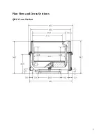
Page 7: ...7 Plan View and Cross Sections QILG Cross Section ...
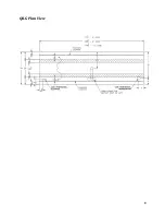
Page 8: ...8 QILG Plan View ...
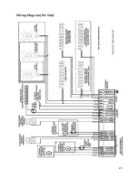
Page 23: ...23 Wiring Diagram Per Side ...
Page 34: ...34 ...
Page 35: ...35 ...


