


13
SECTION: 9
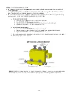
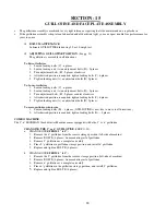
ENTRANCE GUIDE SYSTEM
PURPOSE AND PRECAUTIONS OF THE ENTRANCE GUIDE SYSTEM:
The ENTRANCE GUIDE system is a very important part of this machine. Not only is it used to position material
being fed into the machine, but it also controls the lateral relationship of the material to the forming stations.
ENTRANCE GUIDE CONSISTS OF:
(SEE PG. 13)
A.
RIGHT ENTRANCE GUIDE SHOE
B.
LEFT ENTRANCE GUIDE SHOE
C.
RIGHT LOCKING BOLT
D.
LEFT LOCKING BOLT
E.
LEFT LOCKING COLLARS (5” & 6” POSITIONING STOPS)
F.
RIGHT LOCKING COLLARS (5” & 6” POSITIONING STOPS)
ENTRANCE GUIDE ASSESSMENT:
The RIGHT ENTRY GUIDE (A) controls the amount of material that is fed into the face box and lip box roller
assemblies. It should be moved ONLY to increase or decrease the amount of lip turned under.
If an adjustment is made on the RIGHT ENTRY GUIDE (A), an adjustment must be made on the LEFT ENTRY
GUIDE (B) using coil as a guide. There should be no visible play between the entry guides and the coil. The guide
should not be so tight that it would cause the gutter to bind in the entry guide assembly.
Before moving the RIGHT ENTRY GUIDE (A), always take a measurement from the inside edge of the entry guide
(where the coil will ride) to the inside edge of the frame. This will give a reference point to measure and move
from. You can easily return to your original location if you move the guide in the wrong direction.
TO MOVE THE GUIDES:
1.
Loosen the bolt on the locking collars (C or D).
2.
Move guide
A.
To INCREASE the amount of lip turned under,
Move the guides toward the RIGHT side (FACE side) of the machine.
B.
To DECREASE the amount of lip turned under,
Move the guides toward the LEFT side (BACK side) of the machine.
3.
Retighten the cap screw.
ENTRANCE GUIDE OPERATION
:
When feeding material from the spools on the top of the machine or from a remote station, feed the material straight
into the entry guides. DO NOT FORCE. Continue pushing material into the machine until it stops. The material
can now be jogged through the machine. If the first drive roller does not pull the material into the machine, give the
material a little push from the entrance end while continuing to jog the material into the machine.
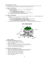
ADJUSTMENT FOR COMBO MACHINE ENTRANCE GUIDES
:
a.
CHANGING ENTRANCE GUIDES FROM 5” TO 6”:
i.
TO MOVE RIGHT GUIDE, loosen LOCKING BOLT C, move guide to the right.
Stop at 6” collar, and tighten BOLT C.
ii.
TO MOVE LEFT GUIDE, loosen LOCKING BOLT D, move guide to the left
Stop at 6” collar, and tighten BOLT D.
b.
CHANGING ENTRANCE GUIDES FROM 6” TO 5”:
i.
TO MOVE RIGHT GUIDE, loosen LOCKING BOLT C, move guide to the left.
Stop at 5” collar, and tighten BOLT C.
ii.
TO MOVE LEFT GUIDE, loosen LOCKING BOLT D, move guide to the right
Stop at 5” collar, and tighten BOLT D.


