background image


TYPE 9112-HEU 

     07/2014 


Fuel 

The appliance is designed for combustion of solid fuel: 
- recommended fuel is wood (max. diameter 190 mm, max. length 450 mm). 
-  the  appliance  also  enables  burning  of  other  kinds  of  solid  fuel  (wood  briquettes,  waste  wood, 
brown  coal  briquettes,  brown  coal  blocks  40  mm).  However  the  operating  conditions  and 
parameters of the appliance may differ from those with the recommended fuel.  Please note that 
the technical characteristics given above were based on a test wood fuel sample and using other 
fuel types will alter these characteristics, energy output, fuel consumption, flue draught etc. 
Make sure that the fuel is dry. It is not recommended to burn high-calorific fuels, which reduce the 
service life of the appliance. 
 

Grate, Grating 

The  purpose  of  the  grate  is  allowing  the  burned  fuel  to  fall  to  the  ashtray,  which  increases  the 
supply of combustion (primary) air to the combustion chamber. It is done by means of the poker 
with the combustion chamber door open. 
After the end of each operation (and cooling down) it is possible to grip the grate lever to move the 
grate back and forth. To remove the pieces which are too big to fall through, rotate the grate a few 
times by means of this lever. 
 

Air Supply Control 

Controlling the supply of primary combustion air is enabled by means of the air rose, which is a 
part of the ashtray door. Turning the rose by means of the rose handle enables precise control of 
air to the combustion chamber and thus alters the speed of fuel combustion (energy output of the 
appliance). 
The secondary combustion air supply can be controlled by means of a lever on the front part of 
the  appliance  (Drawing  1,  point  13).  Air  supply  is  opened  (flap  is  opened)  by  movement  of  the 
lever towards to the front side of appliance and it is closed (the flap is closed) by movement from 
the front side. Movements lock on the lever by neck. 


During the operation of the appliance the supply of the combustion air must be maintained, the air 
supply inlet must not become blocked. Mechanical ventilation/ air extraction must not be used in 
the  room  where  the  appliance  is  placed,  unless  there  is  provided  sufficient  air  supply  for 
ventilation. Ventilation levels are provided in your local building regulations. It is advised to check 
ventilation issues with your local building control office to ensure trouble free operation.  
 

The Ash Extracting Door (Drawing 1, point 6 – Sweeping door) 

When the cooker has been in operation for some time, soot will collect in the cooker parts of the 
draught system (especially where coal has been used). This will eventually affect the draught and 
may create problems while lighting the fire. It will also make operation of the cooker less 
economical, especially when cooking in the oven. 
In the course of cleaning take off the hob top plates, then remove the soot first from the sides  
of the oven walls. Clean all the removed deposits through the ash extracting slot situated under 
the oven door. This can be done simply by using damp newspaper, for example. 


Service Instructions 

Summary of Contents for 9112-HEU

Page 1: ...TYPE 9112 HEU 07 2014 TYPE 9112 HEU OPERATION MAINTENANCE MANUAL INSTALLATION MANUAL SOLID FUEL RANGE COOKER WITH HOT WATER HEATER...

Page 2: ...for contact with foodstuff under all normal conditions or by the stated use of the manufacturer comply with the requirements of Law No 258 2000 Coll the Ministry of Health Decree No 38 2001 Coll and R...

Page 3: ...ntion to fire safety It is forbidden to use the appliance if it is damaged unfit for its function Any contravention of the operating conditions may cause damage to some parts of the appliance It is re...

Page 4: ...o the water to the water range 5 5 kW 3 5 kW Efficiency at NHO 75 Average temperature of flue gas at NHO 190 C Mass flow rate of flue gas at NHO 12 g s Minimum chimney draught 12 Pa Height of the work...

Page 5: ...Storage Drawer 2 Hob Top Plate II 8 Thermometer 3 Oven Door 9 Ash chamber Door 4 Combustion chamber Fire box Door 10 Grate bar 5 Hand Rail 11 Smoke Flap Control 6 Sweeping Door 12 Combustion Air Intak...

Page 6: ...control of air to the combustion chamber and thus alters the speed of fuel combustion energy output of the appliance The secondary combustion air supply can be controlled by means of a lever on the f...

Page 7: ...p panel 3 The single piece glass and ceramic panel You should always use pots with flat bases Drawing 2 Ignition Flap Drawing 3 Is placed below the range and controlled by means of the lever located a...

Page 8: ...utes and perform grating at the same time the combustion performance will improve The appliance output can be controlled by the supply of air under the grate and by the amount and type of fuel When op...

Page 9: ...rinks and 48 hours for food of solid or pasty consistence The Heat Exchange Unit The range cooker with built in heat exchange unit demands more user attention than a standard cooker or a typical boile...

Page 10: ...ng that individual parts fit tightly and seal perfectly Outer surfaces cleaning Clean the appliance after cooling Enamelled surfaces should be cleaned with a damp cloth or sponge and then polished to...

Page 11: ...anufacturer reserves the right to carry out small changes resulting from innovative or technical changes of the product that will have no detrimental affect on the function of the appliance 1 Producti...

Page 12: ...hrough the hob top it is necessary to remove the blanking cap and to attach the flue branch without the ring and use the delivered blank cover to close the rear outlet A chimney with a sufficient drau...

Page 13: ...tive baffle plate shall overlap the protected material up to the nearest wall ceiling made of a fireproof material however not less than 300 mm at the upper side and 150 mm at the lateral sides We rec...

Page 14: ...o use the connection with an open expansion tank in case of some air vaporization from the exchanger If the connection with the expansiomate is used it is necessary to mount a safety valve of 1 8 bar...

Page 15: ...TYPE 9112 HEU 07 2014 14 Dimensional Sketch of the appliance TYPE 9112 All of dimensions are in mm...

Page 16: ...TYPE 9112 HEU 07 2014 15 Installation schematic of the range cooker with a heat exchange unit within the interior of a domestic dwelling...

Page 17: ...TYPE 9112 HEU 07 2014 16 NOTE The valves a pump and other safety accessories are not supplied with the cooker...

Page 18: ...TYPE 9112 HEU 07 2014 17 Spare parts sketch part 1...

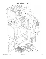
Page 19: ...TYPE 9112 HEU 07 2014 18 Spare parts sketch part 2...

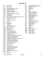
Page 20: ...set 014 Ribbon 040 Chamotte lower panel 015 Plug plastic 041 Grate bearing 016 Ribbon 2 042 Rotatable grate 017 Cover strip 043 Grate bar 018 Oven door with frame 044 Frame set 018A Oven door frame 04...

Page 21: ...TYPE 9112 HEU 07 2014 20...

Page 22: ...112 HEU 07 2014 Producer KVS EKODIVIZE a s plant Dvorce Opavsk 272 793 68 Dvorce u Brunt lu CZECH REPUBLIC phone 420 554 797 111 fax 420 554 745 500 email prodej dvorce kvs ekodivize cz www kvs ekodiv...

Reviews: