VEHICLE TUBING INSTALLATION
1. Mount all components in a suitable location, preferably in a high area above the air system .
Do not mount in engine compartment or near any source of heat or dirt . The system may be
connected to any point in the vehicle's air system .
2. Mount air compressor in a vertical position as shown.
3. CAUTION no condensate or water must be allowed to enter or accumulate in the output of the
Auto Pump . Route output pressure line downward from Auto Pump to permit moisture to drain
away . Water in the pump outlet will induce failure .
4. All connection for air lines are 1/4" NPT . Use Teflon tape, or equivalent on all connections to
insure no leakage of air.
5. The recommended installation of the Auto Pump air compressor system is shown below.
6. Note that an external check valve is located beteen the compressor and the pressure switch.
no additional check valve is required.
7. Mount the air compressor. Connect a suitable piece of flexible tubing from the outlet port of
compressor to the air tank . (Tubing and connectors are not supplied .)
8. An optional Mounting Plate 091-9H-1 is available to reduce any vibration and noise from Auto
Pump and to simplify pump mounting.
NOTE: Compressor must be mounted above air
tank to assure that moisture will flow away from
compressor.
Summary of Contents for Auto-Pump 091-9B-220
Page 7: ...TEMPLATE AUTO PUMP 3 50 4 75 7 32 DIA HOLES 4PLACES ...
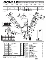
Page 8: ...SPARE PARTS LAYOUT AUTO PUMP ...
Page 16: ...TEMPLATE AUTO PUMP 3 50 4 75 7 32 DIA HOLES 4PLACES ...
Page 17: ...SPARE PARTS LAYOUT AUTO PUMP ...
Page 25: ...TEMPLATE AUTO PUMP 3 50 4 75 7 32 DIA HOLES 4PLACES ...
Page 26: ...SPARE PARTS LAYOUT AUTO PUMP ...
Page 34: ...TEMPLATE AUTO PUMP 3 50 4 75 7 32 DIA HOLES 4PLACES ...
Page 35: ...SPARE PARTS LAYOUT AUTO PUMP ...
Page 43: ...TEMPLATE AUTO PUMP 3 50 4 75 7 32 DIA HOLES 4PLACES ...
Page 44: ...SPARE PARTS LAYOUT AUTO PUMP ...
Page 52: ...TEMPLATE AUTO PUMP 3 50 4 75 7 32 DIA HOLES 4PLACES ...
Page 53: ...SPARE PARTS LAYOUT AUTO PUMP ...
Page 61: ...TEMPLATE AUTO PUMP 3 50 4 75 7 32 DIA HOLES 4PLACES ...
Page 62: ...SPARE PARTS LAYOUT AUTO PUMP ...
Page 70: ...TEMPLATE AUTO PUMP 3 50 4 75 7 32 DIA HOLES 4PLACES ...
Page 71: ...SPARE PARTS LAYOUT AUTO PUMP ...
Page 79: ...TEMPLATE AUTO PUMP 3 50 4 75 7 32 DIA HOLES 4PLACES ...
Page 80: ...SPARE PARTS LAYOUT AUTO PUMP ...
Page 88: ...TEMPLATE AUTO PUMP 3 50 4 75 7 32 DIA HOLES 4PLACES ...
Page 89: ...SPARE PARTS LAYOUT AUTO PUMP ...


