14
OPERATING INSTRUCTIONS
SURFACE MOUNT USING SINE KEYS
Mounting the HDL4 with keys requires the use of sine keys instead of
standard keys. They are available in several different sizes that are listed
on our website at www.kurtworkholding.com. The keys are sold in sets of
2 per package.
English Mounting:
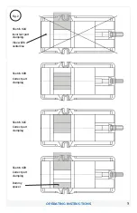
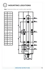
The HDL4 can be properly located using (2) of the four English sine key
holes indicated by the QQ’s in Fig. 5 above. The HDL4 can be bolted down
using the four English 5/16” bolt holes indicated in Fig. 5 above by PP. The
HDL6 vise can also be clamped on the sides toe clamps.
Metric Mounting:
The HDL4 can be properly located using the two Metric sine key holes
indicated by the RR’s in Fig. 5 above. The HDL4 can be bolted down using
the four Metric M8 bolt holes indicated in Fig. 5 above by OO.
PROPER CHIP GUARD INSTALLATION AND USAGE
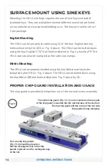
The chip guard is provided to keep chips out of the nut and screw assembly.
Fig.10
The center chip guard (Fig. 10-1) can be inserted so the key part
of the chip guard is inserted into the notched area of the vise bed.
This top chip guard will ride on top of the two side
chip guards during clamping.
The two side chip guards
(Fig. 10-2) should be placed so
that the rectangular hole in the chip
guards is placed over the rectangular peg
on the nut.


