background image

12

 L


 M 

 D 

 K 

 J 

 A 

 WW 

 XX 

 E 

 C 

 O 

 B 

  P [TYP] 

OPERATING INSTRUCTIONS

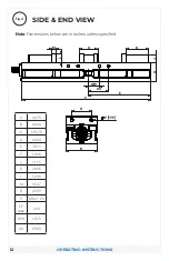
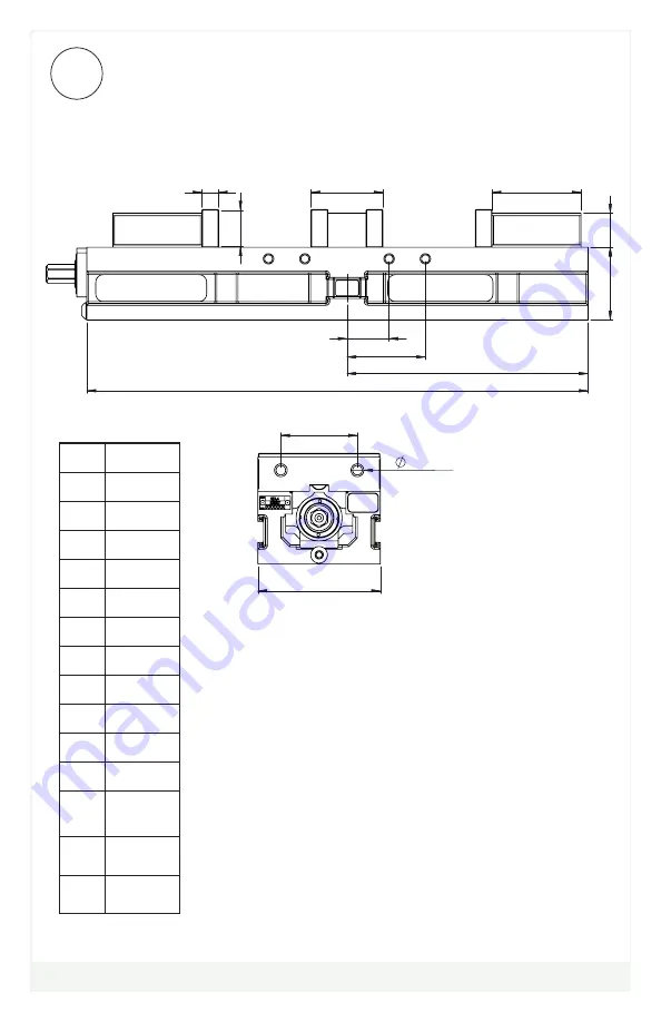
SIDE & END VIEW

A

2.375

B

4.000

C

16.375

D

2.344

E

7.875

F

1.326

J

1.115

K

2.906

L

1.235

M

0.547

O

2.500

P

M8 x 1.25

FF 

Max

3.00

WW

1.375

XX

2.563

Fig.4

Note: 

Dimensions below are in inches unless specified.

Summary of Contents for HDL4

Page 1: ...HDL4 MANUAL ASSEMBLY Operating Instruction Manual HDL4 English HDLM4 Metric ...

Page 2: ...nce Log Notes 20 Warranty 21 VISE DATA Use this to fill out information about your vise for quick reference Purchase Date _________ _________ ___________ Purchase Order _______________________________ Purchased From _______________________________ Delivery Date _______________________________ Serial No _______________________________ NOTE MAKE SURE TO REGISTER YOUR WARRANTY ONLINE AT KURTWORKHOLDI...

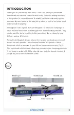
Page 3: ...uch as knee type mills and machining centers They can be used for but are not limited to operations like precision boring drilling tapping finishing The patented Anglock design allows the movable jaw to advance in such a way that each pound of force forward induces a pound of force downward which minimizes the jaw lift and increases accuracy Fig 1 This combined with the needle bearings increases j...

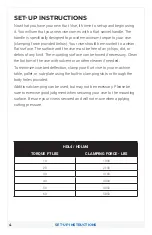
Page 4: ...ing surface can be honed if necessary Clean the bottom of the vise with solvent or another cleaner if needed To minimize vise bed deflection clamp your Kurt vise to your machine table pallet or sub plate using the built in clamping slots or through the body holes provided Additional clamping can be used but may not be necessary Please be sure to exercise good judgment when securing your vise to th...

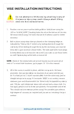
Page 5: ...t the vise by attaching to any of the jaws or injury may result Always attach lifting device to the vise base frame CAUTION NOTE Some of the clamp holes are at inch locations and some are at metric For exact hole locations go to pages 13 14 in this manual 3 After the vise is mounted in place add the vise jaws to the base assembly See jaw installation instructions that came with the jaw kit If a ha...

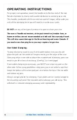
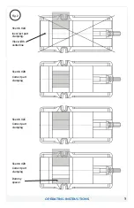
Page 6: ...mping force you may require a larger vise One Sided Clamping To properly clamp a part in your Kurt double station vise you should place the parts in the center of the jaws resting on the ways of the vise Clamping only on one side or above the movable and stationary jaws can result in jaw lift or loss of accuracy See Fig 2 on next page If one sided clamping is necessary you MUST use a dummy part on...

Page 7: ...7 OPERATING INSTRUCTIONS Fig 2 Sketch 2A Incorrect part clamping Vise width centerline Sketch 2B Correct part clamping Sketch 2C Correct part clamping Sketch 2D Correct part clamping Dummy spacer ...

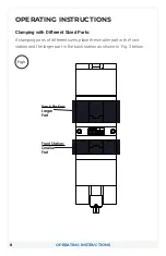
Page 8: ... sizes place the smaller part in the front station and the larger part in the back station as shown in Fig 3 below OPERATING INSTRUCTIONS Fig 3 Back Station Larger Part Front Station Smaller Part M D D C A 3 4 3 4 A B C Q Engineering Engineers Files Levi T Rendering Projects Reference Models ...

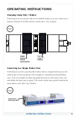
Page 9: ...it includes a mounting plate that bolts to the rear of the vise and holds the back jaw in place The center stationary jaw will need to be removed as well See Fig 5 below OPERATING INSTRUCTIONS Fig 4 Fig 4 Larger Dummy Part in Back Station Part in Front Station Caden Hill 3 3 2021 MINNEAPOLIS KURT DESIGNED MANUFACTURING COMPANY DETAILED CHECKED APPROVED TOOL NAME TITLE MATERIAL OR DESCRIPTION TOLER...

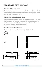
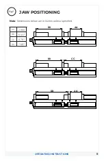
Page 10: ...ndard jaw plates For dimensional information and jaw positioning see Fig 7 and Fig 8 on pages 11 12 Aluminum Carvable Machinable Jaws The Aluminum Carvable jaws come in two different jaw heights 1 40 and 1 90 These jaws can be can be machined in the carvable regions of the jaw See carvable region in Fig 6 to hold curved and contoured shaped parts DO NOT cut into the non carvable region Cast Carvab...

Page 11: ... 6 437 CC 4 781 DD 7 687 Fig 7 C 3 4 3 4 A B Q ENGINEERING ENGINEERS FILES LEVI T RENDERING PROJECTS REFERENCE MODELS AA BB AA 4 00 BB 8 72 CC 5 96 DD 10 69 AA 4 00 BB 8 72 CC 5 96 DD 10 69 DD AA BB CC Note Dimensions below are in inches unless specified ...

Page 12: ... TYP OPERATING INSTRUCTIONS SIDE END VIEW A 2 375 B 4 000 C 16 375 D 2 344 E 7 875 F 1 326 J 1 115 K 2 906 L 1 235 M 0 547 O 2 500 P M8 x 1 25 FF Max 3 00 WW 1 375 XX 2 563 Fig 4 Note Dimensions below are in inches unless specified ...

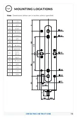
Page 13: ...FF 0 75 GG 0 787 HH 50 mm II II 2 625 KK 5 25 MM 1 5 NN 40 mm OO M8 SHCS PP 5 16 SHCS QQ 0 625 RR 16 mm SS 3 25 TT 1 75 UU 1 25 VV 0 38 Fig 9 PP OO QQ QQ RR FF GG HH HH II KK KK SS TT TT MM NN UU F VV Note Dimensions below are in inches unless specified ...

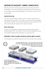
Page 14: ...lso be clamped on the sides toe clamps Metric Mounting The HDL4 can be properly located using the two Metric sine key holes indicated by the RR s in Fig 5 above The HDL4 can be bolted down using the four Metric M8 bolt holes indicated in Fig 5 above by OO PROPER CHIP GUARD INSTALLATION AND USAGE The chip guard is provided to keep chips out of the nut and screw assembly Fig 10 The center chip guard...

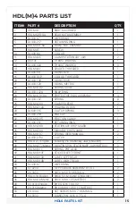
Page 15: ...ING 3 29 DL400 218 END CAP 1 32 HDLM4 225 FRICTION CLAMP 1 33 DL430 231 RETAINING RING 1 34 HDLM4 248 STATIONARY CHIP GUARD 1 35 HDLM4 249 MOVABLE CHIP GUARD 2 36 HDLM4 197 SPRING RED MANUAL 2 37 DL430 273A CLUTCH 1 38 HDL4 277 English Locating Pin Stationary Jaw ENGLISH 2 38 HDLM4 277 Metric LOCATING PIN STATIONARY JAW METRIC 2 39 HDLM4 311 SPRING PRE LOAD 1 40 HDLM4 313F STICKER LEFT FRONT 1 41 ...

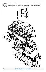
Page 16: ...16 16 20 27 15 10 25 12 13 37 28 7 51 39 32 50 46 26 38 34 35 1 49 33 21 22 36 6 45 14 43 23 5 4 3 29 44 HD 11 24 HDL6 MECHANICAL DRAWING HDL M 4 MECHANICAL DRAWING Fig 11 ...

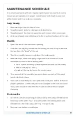
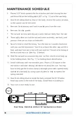
Page 17: ...ut 3 Turn the movable jaw over and clean the inside cavity 4 Remove chips clean and apply a light coat of machine oil to the machined surface of the following item a Nut Screw assembly clean exposed threads on the screw b Bed of vise top of rails c Inside of the vise between the center ways 5 To re assemble the movable jaw press down on each of the quick jaws to lock into place 6 Your vise is now ...

Page 18: ...k the other way until the front and rear front are in line with one another This sets the timing of the front and rear nut See Fig 12 below 10 Slide the nut and screw assembly rear nut first into the vise body up to the holding block See Fig 11 for holding block identification 11 Install stationary and rear movable jaws Place a 3 25 spacer in the rear station and start closing clockwise rotation t...

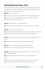
Page 19: ... needed Problem My vise won t hold tolerance Tip You may be experiencing jaw lift from clamping too high or on one side of the jaw Lower the part in the vise jaw and clamp more material Problem My vise is stiff when clamping on a part or is difficult to back off a part Tip The vise s thrust bearing pack may need to be replaced Problem My vise is not clamping at a high clamping force Tip The vise s...

Page 20: ...20 MAINTENANCE LOG NOTES MAINTENANCE LOG NOTES ...

Page 21: ...d to the replacement or repair of any Kurt product or part by an authorized Kurt technician which are returned to Kurt Manufacturing Company s place of business or any authorized service center transportation shipping and postal charges prepaid and there determined by Kurt Manufacturing Company to be covered by the warranty contained herein THE LIMITED WARRANTY DESCRIBED HEREIN IS MADE EXPRESSLY I...

Page 22: ...any feedback or questions please contact us at Kurt Industrial Products A Division Of Kurt Manufacturing 9445 East River Road NW Mpls MN 55433 Phone 763 574 8309 Toll Free 877 226 7823 Fax 763 574 8318 Toll Free Fax 877 226 7823 kurtworkholding com workholding kurt com ...

Reviews: