background image

Service Manual

17

For internal use only

Step 4

The display will automatically show the 

temperature of the NTC

sensor no. 2 in °C as shown on the right.

Check the NTC sensor if an abnormal temperature is shown:

55k

Ω

 for 20°C, 4.7k

Ω

 for 90°C.

If not, press the plus button once to move on to 

Step 5

The display will automatically light up as shown on the right in order

to indicate that 

all of the elements are being supplied with

electricity.

Press the plus button once to move on to 

Step 6

The steam generation symbol will blink. The heater will switch on.

Check

the safety thermostat I = 0

the wiring I = 0

the steam generator resistance I = 0

the circuit board I = 0

Press the plus button once to move on to 

Step 7

Normally the valve will have supplied the heating element with

water. If this process has not yet been completed, 

VANN ON

 will

appear in the display. If the display shows 

VANN OFF

 open the door

of the oven and check the water.

Attention!

The oven door will need to be opened in order to continue.

Once the oven door has been opened and closed, press the plus button once and proceed to 

Step 8

The cross-flow fan and the electric heating pad remain switched

on. Open the door and check the temperature of the top of the

oven. The ceiling of the inside of the oven must be very hot.

Check the wiring and the electric heating pad if it is not hot. The

reading must be around 350

Ω.

Press the plus button once to move on to 

Step 9

Ver ON

 will appear in the display to indicate that the thermistor is

switched on. The flap will close slowly. Should 

Ver on 

not be

indicated in the display, check the power supply of the activator

and the resistance (1k

Ω)

.

Press the plus button once to move on to 

Step 10

Close the program.

Summary of Contents for EDG 6500.0

Page 1: ...Steam Cooker EDG 6500 0...

Page 2: ...e Manual H3 63 02 Responsible Dieter Rutz K PPERSBUSCH HAUSGER TE AG Email dieter rutz kueppersbusch de Phone 0209 401 733 Kundendienst Fax 0209 401 743 Postfach 100 132 Date 23 10 2006 45801 Gelsenki...

Page 3: ...5 User settings and functions 10 5 1 Setting the time of day 10 5 2 Characteristics 10 5 3 Lock child safety device 10 5 4 Cleaning the water channel 10 6 Cooking cycle 11 7 Structure subassembly stru...

Page 4: ...nd wire resistance must not exceed that specified in the standard It is of vital importance for ensuring the safety of people and the functioning of the appliance On completion of repairs an inspectio...

Page 5: ...re maintained food does not lose its structure There is therefore almost no need to add salt and spices To sum up cooking with steams makes conscious healthy eating possible without any extra effort T...

Page 6: ...fuse Should the plug not be accessible subsequent to installation a universal disconnection device with a contact clearance of at least 3mm must be available at the installation point in order to ful...

Page 7: ...ough this cut out 2 Position the appliance and align it horizontally 3 Slide the oven right into the cabinet niche Do not jam the lead of the appliance 4 Check to ensure that the appliance has been pr...

Page 8: ...system The principle is not the same as for cooking in a pressure cooker since here the internal pressure exceeds the atmospheric pressure The steam oven firstly fills up with steam and the temperatur...

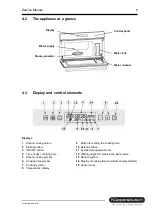
Page 9: ...time 5 Steam cooking symbol 6 Cooking time symbol 7 Cooking symbol 8 Temperature display 9 Button for setting the cooking time 10 Selector button 11 Symbol for separate timers 12 Warning signal for fa...

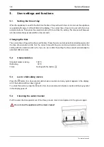
Page 10: ...time shown starts to blink Set the correct time with the plus and minus buttons and confirm the setting with the selection button 10 If you do not confirm the setting the time set will automatically b...

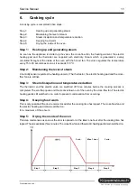
Page 11: ...s the heating element The thermistor the electric heating pad and the cross flow fan are still live Step 3 Steam dissipation and temperature reduction The thermistor and the electric valve are switche...

Page 12: ...12 Service Manual For internal use only Air circulation steps 1 to 4...

Page 13: ...with food 7 2 Electric valve The electric valve supplies the steam generator with water Technical data 220 240V 2l min 3 7k 7 3 Steam generator The steam generator converts water to steam The condensa...

Page 14: ...hermistor keeps the vent flap closed while the oven is in operation Technical data 220 240V 5W 1k 7 7 Door switch The door switch enables the cooking cycle to be changed when the door is open Door ope...

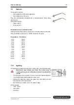
Page 15: ...ance 20 C 58k 30 C 39k 40 C 32k 50 C 25k 60 C 18k 70 C 12k 80 C 9k 90 C 7k 100 C 5k 110 C 3 5k 120 C 2 5k 130 C 2k 7 10 Lighting The light bulb is located inside the oven at the back on the right hand...

Page 16: ...gram sequence Press any button apart from the plus and minus buttons to exit the test program If no button is pressed the program will automatically be exited after 3 minutes Step 1 The display will a...

Page 17: ...element with water If this process has not yet been completed VANN ON will appear in the display If the display shows VANN OFF open the door of the oven and check the water Attention The oven door wi...

Page 18: ...ace card and the display card If error code E1 appears all of the power elements will be switched off E2 Sensor off or short circuited E3 Problems with the water cycle Power elements will be switched...

Reviews: