background image

6.2


Initial Setup 

6.2.1


Setting up initial position using RobovieMaker2 


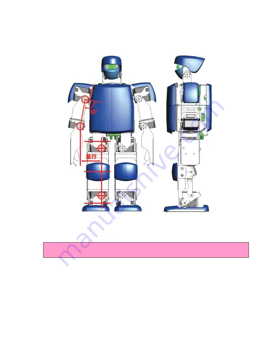
Before start using the robot or after long use of the robot, the angle of the joint might change.  
Please setup the initial position by using RobovieMaker2.   The detailed instruction to setup initial 
position is explained in RobovieMaker2 User Manual. 

<!> Please hold the robot body when you turn the robot power on.  If you are holding the part 
close to the joints, you might pinch your fingers. 


Summary of Contents for KTX-PC

Page 1: ...KTX PC User Manual KumoTek 06 25 2010 Tech Support Masahiro Ishida...

Page 2: ...d information 2 Safety Robot has tremendous power on each servo mounted on his joints and improper use of the robot may result in serious injuries Please follow safety issues below Please hold his bod...

Page 3: ...3 Features and Specification 3 1 Name of the Components and Features Front...

Page 4: ...3 2 Name of the Components and Features Top View...

Page 5: ...820 Intel Atom Z530 1 6GHz Storage CF Flash Memory 8GB Secondary CPU VS RC003HV ARM7 60MHz Sensor USB Camera VS IX001 2 axel gyro sensor and 3 axel accelerometer Exterior Shock absorbing material Spea...

Page 6: ...3 4 Joints...

Page 7: ...attery charger to wall power supply Make sure that no battery is connected to the charger 2 Connect battery to the charger by using connection cable The LED will turn into red It will take about 2 hou...

Page 8: ...able You can connect up to 2 USB devices 1 VGA and 1 LAN If you are connecting USB HDD or USB CD DVD Drive please use them on self power mode If you are running the robot with that hardware connected...

Page 9: ...e picture The sign represents ON and o represents OFF White LED next to the switch comes on when the power applied 5 3 2 Turning on the PC power switch You can turn on the PC board by the PC power swi...

Page 10: ...5 4 Internal connection diagram...

Page 11: ...ion Please use latest version of RobovieMaker2 version 9 or version 10 is currently supporting KTX PC and KTX PC Pro 6 1 2 Controlling Servo Controller VS RC003 from internal PC 6 1 2 1 USB Communicat...

Page 12: ...obot the angle of the joint might change Please setup the initial position by using RobovieMaker2 The detailed instruction to setup initial position is explained in RobovieMaker2 User Manual Please ho...

Page 13: ...6 3 Creating Motion Detailed instruction is on RobovieMaker2 User Manual...

Page 14: ...up again Please use command Ctrl Alt F1 to go back to the normal display CRT If the command is still not make you go back to the normal display then you might have setup a login password Try entering...

Page 15: ...ables is to use the nylon tie straps as depicted Be sure to replace these straps after they become worn down or lost This method is highlighted in green 7 2 Protecting Motors When configuring the robo...

Page 16: ...asing and the metal frame DO NOT allow the servo casing to touch the metal casing The gap between the servo casing and metal frame is highlighted in blue in the picture above Note If this occurs quick...

Reviews: