background image

- 8 -

3. Connect test leads to device or circuit being

measured.

4. Turn on power of the device or circuit being

measured voltage value will appear on Digital

Display along with the voltage polarity.

DC CURRENT MEASUREMENT

1. Red lead to “INPUT”. Black lead to “COM” (for

measurements between 200mA and 10A connect red

lead to “10A” jack with fully depressed.)

2. RANGE switch to desired DCA range.

3. Open the circuit to be measured, and connect test

leads INSERIES with the load in with current is to

measure.

4. Read current value on Digital Display.

5. Additionally, “10A” function is designed for

intermittent use only. Maximum contact time of the

test leads with the circuit is 15 seconds, with a

minimum intermission time of seconds between

tests.

RESISTANCE MEASUREMENT

1. Red lead to “INPUT”. Black lead to “COM”.

2. RANGE switch to desired Ω range.

3. If the resistance being measured is connected to a

circuit, turn off power and discharge all capacitors

before measurement.

4. Connect test leads to circuit being measured.

5. Read resistance value on Digital Display.

Summary of Contents for DT132F

Page 1: ...OPERATOR S INSTRUCTION MANUAL DIGITAL MULTIMETER READ AND UNDERSTAND THIS MANUAL BEFORE USING THE INSTRUMENT WARNING MODEL DT132F CE CAT III 600V TRUE RMS BACK LIGHT ...

Page 2: ...g measurement is conducted to prevent damage of the Meter When the Meter working at an effective voltage over 60V in DC or 30V rms in AC special care should be taken for there is danger of electric shock Use the proper terminals function and range for your measurements Do not use or store the Meter in an environment of high temperature humidity explosive inflammable and strong magnetic field The p...

Page 3: ...the battery when not using for a long time Constantly check the battery as it may leak when it has been using for some time replace the battery as soon as leaking appears A leaking battery will damage the Meter 1 General Specifications Display LCD 3999 counts updates 2 sec LCD Size 55 x 31mm Polarity Indication displayed automatically Over range Indication OL displayed Low Battery Indication displ...

Page 4: ...w battery Fuse Diode Continuity test C Centigrade F Fahrenheit Conforms to European Union directive Double insulated APO auto power off data hold LCD RANGE switch 10A jack VΩmA jack COM jack Back Light Button Hold Button ...

Page 5: ...OTECTION 220V rms AC for 200mV range and 600V DC or 600V rms for all ranges AC VOLTAGE RANGE RESOLUTION ACCURACY 200V 100mV 500V 1V 2 0 of rdg 10D RESPONSE Average responding calibrated in rms of a sine wave FREQUENCY RANGE 45Hz 450Hz OVERLOAD PROTECTION 600V DC or 600V rms for all ranges AUDIBLE CONTINUITY RANGE DESCRIPTION Built in buzzer sounds if resistance is less then 30 20Ω OVERLOAD PROTECT...

Page 6: ... Accuracy 200µA 0 1µA 1 5 of rdg 8dgts 2000µA 1µA 20mA 10µA 200mA 100µA 2A 1mA 2 0 of rdg 4dgts 10A 10mA Overload Protection µA and mA ranges F0 5A 600V fuse 4A and 10A ranges F10A 600V fuse Max Input Current INPUT jack 200mA A jack 10A For measurements 5A duration 10 seconds interval 15 minutes Voltage Drop 400µA 40mA and 4A ranges 20mV 4000µA 400mA and 10A ranges 200mV Frequency Range 40Hz 400Hz...

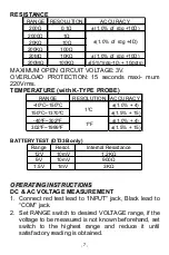
Page 7: ...TION ACCURACY 40ºC 150ºC 1 0 4 150ºC 1370ºC 1 5 15 40ºF 302ºF 1 0 4 302ºF 1999ºF 1 5 15 1ºC 1ºF BATTERY TEST DT33B only Range Resol Internal Resistance 12V 10mV 1 2KΩ 9V 10mV 900Ω 1 5V 1mV 3KΩ OPERATING INSTRUCTIONS DC AC VOLTAGE MEASUREMENT 1 Connect red test lead to INPUT jack Black lead to COM jack 2 Set RANGE switch to desired VOLTAGE range if the voltage to be measured is not known beforehand...

Page 8: ...d connect test leads INSERIES with the load in with current is to measure 4 Read current value on Digital Display 5 Additionally 10A function is designed for intermittent use only Maximum contact time of the test leads with the circuit is 15 seconds with a minimum intermission time of seconds between tests RESISTANCE MEASUREMENT 1 Red lead to INPUT Black lead to COM 2 RANGE switch to desired Ω ran...

Page 9: ... Temperature value ºC or ºF NOTE The TP 01 K type thermocouple Max Operating temperature of Probe 250 C 482 F 300 C 572 F short term The sensor supplied with the instrument is an ultra fast response naked bead thermocouple suitable for many general purpose applications AUDIBLE CONTINUITY TEST 1 Red lead to INPUT Black lead to COM 2 RANGE switch to range 3 Connect test leads to two points of circui...

Page 10: ...to be tested set the range switch to the desired BATT range 3 Connect the test leads to the battery to be tested 4 Read the reading on the display The polarity of the red test lead connection will be indicated ...

Page 11: ...e battery Fuse 500mA 600V or 10A 600V remove the 2 screws in the bottom of the case simply remove the old and replace with a new one Be careful to observe polarity ACCESSORIES Operator s instruction manual Set of test leads Gift box TP01 K type thermoelectric couple 1 5V x 3 AAA size Any problem you also could write the email to 2968379892 qq com we are always here for you thanks PN 31 11 3304 ...

Reviews: