Kühtreiber MAKin 320 P HF Manual Download Page 30

30 

|

EN

Table 4

s (mm)

a (mm)

d (mm)

α (°)

0 - 3

0

0

0

3

0

0.5 (max)

0

4 - 6

1 - 1.5

1 - 2

60

Basic rules during welding by TIG method:

1. 

Purity - grease, oil and other impurities must be removed from the weld 

during welding. It is also necessary to mind purity of additional material 

and clean gloves of the welder during welding.

2. 

Leading  additional  material  -  oxidation  must  be  prevented.  To  do  so, 

flashing end of additional ma-terial must be always under the protection 

of gas flowing from the hose.

3. 

Type and diameter of tungsten  electrodes - it is necessary to choose them 

according to the values of the current, polarity, type of basic material and 

composition of protective gas.

4. 

Sharpening of tungsten electrodes - sharpening the tip of the electrode 

should be done in trav-erse/horizontal direction. The tinier the roughness 

of the surface of the tip is, the calmer the burning of the el. arc is as well 

as the greater durability of the electrode is.

5. 

The amount of protective gas - it has to be adjust-ed according to the type 

of welding or according to the size of gas hose. After finishing the welding 

gas must flow sufficiently long to protect material and tungsten electrode 

against oxidation.

Typical TIG welding errors and their impact on weld quality:

The welding current is too -

Low:

 unstable welding arc

High:

 Tungsten electrode tip breaks lead to turbulent arcing.

Further, mistakes may be caused by poor welding torch guidance and poor 

addition of additive material.

Welding in method MMA

Switch the machine to MMA mode - coated electrode. Table 5 lists the ge-

neral values for the choice of the electrode, depending on its diameter and 

the thickness of the base material. These data are not absolute and are in-

formative only. For exact selection, follow the instructions provided by the 

manufacturer of the electrodes. The current used depends on the position 

of the welding and the joint type and increases according to the thickness 

and dimensions of the part.


Table 5


Thickness of welded material (mm)  

Diameter of the Electrode

1.5 - 3

2

3 - 5

2.5

5 - 12

3.25

> 12

4

Table 6: Setting the welding current for the given electrode diameter

Diameter of the Electrode (mm)

Welding Current (A)

1.6

30 - 60

2

40 - 75

2.5

60 - 110

3.25

95 - 140

4

140 - 190

5

190 - 240

6

220 - 330

The approximate indication of the average current used for welding with 

ordinary steel electrodes is given by the following formula:

I = 50 x (Øe – 1)

where:  I  =  the  intensity  of  the  welding  current  e  =  the  diameter  of  the 

electrode

Example for an electrode with a diameter of 4 mm: 

I = 50 x (4 - 1) = 50 x 3 = 150 A

Correct electrode holding during welding

45°

β

45° +70°

Picture 7

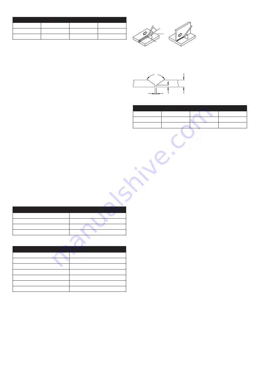
Preparation of basic material:

Table  7  lists  the  material  preparation  values.  Specify  the  dimensions  as 

shown in Figure 8.

a

s

α

d

Picture 8


Table 7

s (mm)

a (mm)

d (mm)

α  (°)

0 - 3

0

0

0

3 - 6

0

s/2 (max)

0

3 - 12

0 - 1.5

0 - 2

60

Warning about possible problems and their remedy

The extension cord and welding cables are considered the most common 

cause of the problem. 

If you have any problems, follow these steps:

•  Check the value of the supplied mains voltage.

•  Make sure that the power cord is fully connected to the power outlet and 

the main power switch.

•  Make sure the fuses or the circuit breakers are OK.

If  you  are  using  the  extension  cable,  check  its  length,  cross-section  and 

connection.

Make sure the following parts are not defective:

•  Main switch of the grid

•  Power socket and main power switch

Routine maintenance and inspection

Check according to EN 60974-4. Always before Use the machine to check the 

condition of the welding and supply lines cable. Do not use damaged cables.

Perform a visual check:

•  welding cables

•  power grid

•  welding circuit

•  covers

•  control and indicator elements

•  general status

Summary of Contents for MAKin 320 P HF

Page 1: ...1 N VOD K OBSLUZE SVA OVAC STROJ INSTRUCTION FOR USE WELDING MACHINE CZ EN MAKin 320 P HF AC DC...

Page 2: ...visn organizaci kter m dostupn p slu n vy baven a speci ln vy kolen person l Ve ker na e stroje a za zen jsou p edm tem dlouhodob ho v voje Proto si vyhrazujeme pr vo na zm nu b hem v roby Popis Stroj...

Page 3: ...lkov ovl d n UP DOWN 10k potenciometr bezdr tov ovl d n Chlad c modul ANO Gener tor ANO TIG DC P edfuk plynu s 0 2 Startovac proud A ANO UP SLOPE s 0 10 DOWN SLOPE s 0 10 Koncov proud A ANO Dofuk plyn...

Page 4: ...ut PULS bodov n Pozice 12 Deaktivace vodn ho chlazen Pozice 13 Aktivace vodn ho chlazen Pozice 14 P ep n n zp sobu chlazen Pozice 15 P ep n n re im Pozice 16 P ep n n funkc Pozice 17 Ovl dac n kod r P...

Page 5: ...e prov d pomoc ovl dac ho n kod ru Pro nastaven je nutn m t aktivn funkci nastaven sva ovac ho proudu Aktiva ce se prov d postupn m stisknut m ovl dac ho n kod ru Kontrolka hl proudu Nastaven sva ovac...

Page 6: ...e prov d po stupn m stisknut m ovl dac ho n kod ru MMA Nastaven funkce ANTI STICK p ilepen elektrody Funkce sni uje sva ovac nap t na 5 V p i vyhodnocen zkratu na v stupn ch svork ch p i p ilepen elek...

Page 7: ...li n mu zah v n wolframov elektrody a n sledn tvorb kuli ky na jej m konci N sledkem vytvo en kuli ky doch z k nestabiln mu ho en sva ovac ho oblouku a ztr ty mo nosti zen sm ru oblouku Pokud jsou ve...

Page 8: ...Aktivac t to funkce doch z ke sn en tepeln ho zat en sva ovan ho ma teri lu Aktivace se prov d postupn m stisknut m ovl dac ho n kod ru TIG HF Ovl dac n kod r TIG AC triangl TIG AC kvadr t TIG AC sinu...

Page 9: ...postupn m stisknut m ovl dac ho n kod ru TIG HF Ovl dac n kod r Sva ovac proud TIG DC Kontrolka hlavn ho proudu TIG DC Nastaven funkce PRE GAS p edfuk plynu Funkce slou k zaji t n ochrann atmosf ry p...

Page 10: ...ru po ukon en sva ovac ho procesu a z rove chlad wolframovou elektrodu N zk doba trv n funkce m e m t vliv na kva litu zapalov n sva ovac ho oblouku z d vodu oxidace elektrody Aktivace se prov d postu...

Page 11: ...pulzu doch z ke sn en tepeln deformace materi lu a z en svarov l zn Aktivace se prov d postupn m stisknut m ovl dac ho n kod ru TIG HF Ovl dac n kod r TIG DC TIG DC Vypnut funkce PULSE SPOTWELDING Op...

Page 12: ...tepeln ho zat en i penetrace sva ovan ho materi lu TIG HF Ovl dac n kod r TIG DC TIG DC SPOT Nastaven funkce POST GAS dofuk plynu Funkce zaji uje ochranu svaru po ukon en sva ovac ho procesu a z rove...

Page 13: ...en ch postup 3 Stiskn te tla tko na ho ku 4 Pro ukon en sva ovac ho procesu uvoln te tla tko na ho ku Pr b h sva ovac ho procesu u TIG HF obr 1 1 P ibl en wolframov elektrody ke sva ovan mu materi lu...

Page 14: ...lektrody Spr vnou volbou wolframov elektrody a jej p pravou ovlivn me vlastnosti sva ovac ho oblouku geometrii sv ru a ivotnost elektrody Elektrodu je nut n jemn brousit v pod ln m sm ru dle obr zku 4...

Page 15: ...ov n b n oceli a n zkolegovan ch slitin Tyto daje nemaj absolutn hodnotu a jsou pouze informativn Pro p esn v b r sledujte in strukce poskytovan v robcem elektrod Pou it proud z vis na pozici sv e n...

Page 16: ...Sva ovac kabely nejsou p ipojeny P ipojte oba sva ovac kabely Sva ovac kabely jsou po kozeny Opravte vym te po kozen kabel Zemn c kabel nen p ipojen Zkontrolujte p ipojen zemn c ho kabelu 6 Oblouk lze...

Page 17: ...appropriate equip ment and specially trained personnel All our machines and equipment are subject to long term development Therefore we reserve the right to make changes during production Description...

Page 18: ...control UP DOWN 10k potentiometer wireless control Cooling unit Yes Generator Yes TIG DC PRE GAS s 0 2 Starting current A ANO UP SLOPE s 0 10 DOWN SLOPE s 0 10 End Current A Yes POST GAS s 0 10 Pulse...

Page 19: ...LS function Position 11 Switching off PULS SPOT Position 12 Deactivate liquid cooling Position 13 Activate water cooling Position 14 Control button Position 15 Switching modes Position 16 Function swi...

Page 20: ...ng function must be active for the setting Activation is done by pressing the control n encoder one after the other Main current indicator Welding current setting MMA method N coder Welding current MM...

Page 21: ...at is active for the set time After the set time has elapsed the welding arc ignites Activation is performed by pressing the control n coder one after the other TIG HF N coder TIG AC triangle wave TIG...

Page 22: ...at and subsequently form a ball at its end As a result of the formation of a ball the welding arc becomes unstable and the possibility of controlling the arc direction is lost If black spots are visib...

Page 23: ...TIG HF N coder TIG AC triangle wave TIG AC square wave TIG AC sinusoid wave TIG AC Turn off the PULSE function Press the mode switch repeatedly to the OFF position TIG HF N coder TIG AC triangle wave...

Page 24: ...tivates the function that is active for the set time After the set time has elapsed the welding arc ignites Activation is performed by pressing the control n coder one after the other TIG HF N coder T...

Page 25: ...DC Setting the 2 STROKE function The function indicates how the welding process is activated When using this mode it is necessary to press the control button during welding to send a signal to activa...

Page 26: ...mode switch repeatedly to the OFF position TIG HF N coder TIG DC TIG DC Setting the CYCLE function The function allows switching between two currents Activation is only possi ble in 4 stroke mode TIG...

Page 27: ...Setting POST GAS function The function ensures protection of the weld after the welding process is com pleted and at the same time it cools the tungsten electrode The low duration of the function can...

Page 28: ...hing the tungsten electrode to the welded material 2 Press the button on the burner high frequency HF to ignite the arc 3 Welding process 4 Finishing the welding process and activating the DOWN SLOPE...

Page 29: ...in Figure 4 Figure 5 shows the effect of grinding the electrode on its service life Picture 4 Picture 5 Figure 5A Fine and even grinding of the electrode in the longitudinal direction Lifetime up to 1...

Page 30: ...low the instructions provided by the manufacturer of the electrodes The current used depends on the position of the welding and the joint type and increases according to the thickness and dimensions o...

Page 31: ...the machine 5 The arc cannot be ignited The welding cables are not connected Connect both welding cables The welding cables are damaged Repair replace damaged cable The ground cable is not connected C...

Page 32: ...Termistor Thermistor 23 Hlavn transform tor Main transformer 25 Dno Bottom Seznam n hradn ch d l List of spare parts Popis Description 26 PCB kondenz tor PCB condenser 27 PCB n sobi PCB multiplier 28...

Page 33: ...4 Typ stroje Machine type 5 Jm no a adresa v robce Name and address of manufacturer 6 V robn slo Serial number 7 Normy Standards 8 Proud p i zat en Load current 9 Nap t p i zat en Voltage under load...

Page 34: ...34 Elektrotechnick sch ma Electrical scheme...

Page 35: ...robku Type MAKin 320 P HF AC DC V robn slo stroje Serial number V robce Producer Raz tko OTK Stamp of Technical Control Department Datum Date of production Kontroloval Inspected by Z znam o proveden...

Page 36: ...36 V robce si vyhrazuje pr vo na zm nu The producer reserves the right to modification 04 2020...

Reviews: