background image

- 19 -

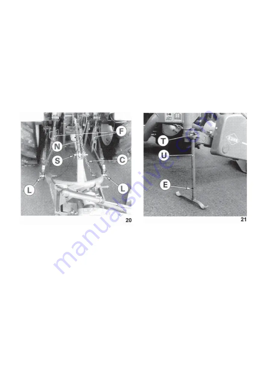
1. Back the tractor to the mower and attach the lower links to the hitch pins. Secure the links with lynch pins

shown at "L" (photo 20).

2. Check that the 2 lift rods (F) are adjusted at the same length.

3. Attach the top link (N) using the pin (S) provided (photo 20). Two positions are available on the pin, depending

on the diameter of the ball joint, to secure the link to the mower.

4. Connect the hydraulic hose to the tractor if the unit is equipped with the hydraulic lift. See optional equipment

for adaptors having different threads.

5. Raise the mower with the tractor hydraulics and depress the pin (T) (photo 21) and raise the parking stand

(U). Lock stand in notch (E) during transport and field operation.

Summary of Contents for GMD 55

Page 1: ...ASSEMBLY OPERATOR S MANUAL GMD 44 55 66 SELECT MULTIDISC MOWER N 95011 A GB 07 98...

Page 2: ...instruct you on the general operation of your machine He is interested that you get the best performance possible and will be glad to answer any special questions that may arise regarding the operati...

Page 3: ...___________________________ 21 Lowering the cutterbar and adjustments for work ______________ 22 Operating the mower ____________________________________ 24 Parking the machine _______________________...

Page 4: ...n is at the risk and responsibility of the operator Designated use of the machine also means following operation maintenance and repair recommendations given by the manufacturer using only genuine spa...

Page 5: ...eginning work check the surrounding area beware of children Make sure there is sufficient visibility Keep all people and animals away from the danger zone of the machine risk of projection 8 Carrying...

Page 6: ...ntion to machine overhang length height and weight 22 Before operating the machine ensure that all safety guards are firmly in place and in good condition If worn or damaged replace immediately 23 Bef...

Page 7: ...themachinewithnarrowwheeltracktractorswhenworkingortransportingonunevenorsloping terrain POWER TAKE OFF 1 Only use PTO shaft supplied with the machine or recommended by the manufacturer 2 PTO guards m...

Page 8: ...e circuits are not under pressure 4 It is strongly recommended that the operator marks the hydraulic connections between tractor and machine to avoid making a wrong connection WARNING Functions could...

Page 9: ...ore any electric welding is carried out on tractor or attached machine disconnect generator and battery terminals 10 Repairs on elements under pressure or tension springs accumulators etc must only be...

Page 10: ...ged unless the cutterbar skid shoes are in contact with the ground and the protective cover is folded down 11 Ground of the pastures to be mown must be free of foreign objects 12 Even when the machine...

Page 11: ...BEEN PLACED ON YOUR MACHINE IN THE AREAS INDICATED THEY ARE INTENDED FOR YOUR PERSONAL SAFETY AND FOR THE SAFETY OF THE PEOPLE WORKING WITH YOU THE TEXT SHOWN ON THEM GIVES THEIR PRECISE MEANING KEEP...

Page 12: ...10...

Page 13: ...tractor should be 30 hp minimum for the GMD 44 SELECT 40 hp minimum for the GMD 55 SELECT and 45 hp minimum for the GMD 66 SELECT Insufficient tractor horse power may cause stripping and poor cutting...

Page 14: ...spacer bolts B taped on the check chain Torque to 5 daNm 40 ft lbs Unscrew nut E place plate F in proper position add a washer dia 16 x 30 x 3 and refit nut E photo 3 Install the belts D tighten them...

Page 15: ...nd to the 3 point frame yoke P using the pin Q and 2 roll pins R diameter 6 x 45 as shown in photo 6 4 Mounting the inner shoe Attach the inner shoe S using the 4 lower positions with 2 self locking b...

Page 16: ...k nut photo 10 Then tighten the 4 bolts L photo 9 of the frame pipe to 14 daNm 100 ft lbs Attach frame pipe T to the gearbox with 4 self locking bolts L M 12 x 35 tighten to a torque of 14 daNm 100 ft...

Page 17: ...M 10 photo 13 7 Mounting the swath board Attach the swath board at O with one carriage bolt M 12 x 80 spring dished washer and lock nut photo 14 Tighten nut enough so swath board can still pivot free...

Page 18: ...fig 15 Then attach the pre assembled front safety bar B at N with hexagonal screws M 12 x 75 and self locking nuts M 12 photo 16 Do not tighten these screws completely so that the front safety bar can...

Page 19: ...24 x 2 to attach the following components on the outside arms of the safety bars safety guard locking device S safety cover D stop rod J on GMD 44 and 55 SELECT fig 15 Note Make sure that the pivot ax...

Page 20: ...ing Follow fig 2 for category 1 tractors with standard wheel track After removing the roll pin E and the support chain R turn the right lower hitch pin T over to adapt the machine to category 1 tracto...

Page 21: ...d photo 20 Two positions are available on the pin depending on the diameter of the ball joint to secure the link to the mower 4 Connect the hydraulic hose to the tractor if the unit is equipped with t...

Page 22: ...not the case shorten the two transmission tubes and the two guard tubes by the same length fig 22 and 23 Bevel and clean the tubes fig 24 and grease the inside of the outer tube fig 25 3 Never operat...

Page 23: ...rrow 1 supplied with the machine and fold the front safety bar upwards arrow 2 photo 28 till it is automatically locked in transport position 5 Lift the cutterbar with the hydraulic lift or the mechan...

Page 24: ...em NOTE Cutterbar must be in raised or transport position 2 Remove the transport rod T from the 3 point frame and secure it with both ends on the protective cover frame using the R clip L photo 31 3 L...

Page 25: ...n is encountered If the cutterbar continues to break away the spring R photo 34 can be tightened to increase the breakaway pressure Normally for the GMD 44 SE LECT the overall spring length A should b...

Page 26: ...w a few minutes for oil to spread in the cutterbar before engaging PTO when changing cutterbar from transport to operating position Before cutting engage tractor PTO and slowly increase speed up to 54...

Page 27: ...K KEEP ALL PERSONS AND ANIMALS FROM THE DANGER ZONE OF THE MACHINE RISK OF PROJEC TION FOR YOUR SAFETY ONLY PARK THE MACHINE WITH THE CUTTERBAR IN THE HORI ZONTAL POSITION PARKING THE MACHINE To park...

Page 28: ...C serves as a check plug when the bar is horizontal Remove plug C When oil level is correct it will just begin to flow out of the hole Plug C is also used as a drain plug when the cutterbar is in the...

Page 29: ...ECOMMENDED GREASE AND OIL CHANGE PERIODS ARE BASED ON NOR MAL FIELD AND WORK CONDITIONS SEVERE OR UNUSUAL CONDITIONS MAY REQUIRE MORE FREQUENT LUBRICATION OR OIL CHANGES RESPECT SPECIFIED OIL QUANTITI...

Page 30: ...e forces IMPORTANT REPLACE FIXING NUTS AND BOLTS AFTER HAVING BEEN REUSED A MAXI MUM OF 5 TIMES ATTENTION ALWAYS REPLACE DAMAGED KNIVES NEVER STRAIGHTEN A BENT KNIFE NEVER REPLACE ONE KNIFE ONLY PER D...

Page 31: ...PARTS IF WORN OR DAMAGED 2 TO CARRY OUT SUCH OPERATIONS AS LUBRICATION CLEANING UNBLOCKING OR ANY ADJUSTMENTS STOP THE TRACTOR ENGINE REMOVE IGNITION KEY AND DISCONNECT THE PTO SHAFT UNLESS OTHERWISE...

Page 32: ...quality risk of damage to the cutterbar 2 Worn knives The width B of a knife measured at a distance of 10 mm away from the edge of the disc should be greater than 3 4 the nominal width of the knife T...

Page 33: ...er oil or dirt When wear on the head reaches the contact area of the knife When the diameter D of the bolt shoulder is less than 15 mm for a hole of 18 mm 13 mm for a hole of 16 mm 2 The nuts must be...

Page 34: ...6000 GMD 66 reinforced disc and knife kit 103 6040 WEAR PLATE fig 49 To prolong the life of worn disc guards when working in very difficult and abrasive conditions wear plates are available through o...

Page 35: ...assembly no 101 6090 photo 53 HYDRAULIC ADAPTATORS photo 54 For fitting to different types of hydraulic connectors three adaptators are available M 16 x 1 5 1 2 GAZ CON 22 no 823 012 05 1 2 NPT 24 no...

Page 36: ...the GMD 55 SELECT the first disc or the first and second discs can be replaced by one to two discs with cones photo 58 When replacing disc tighten correctly self locking nut Q fig 45 18 daNm 130 ft l...

Page 37: ...Clean mower 2 Drain oil from gearbox and cutterbar and refill with clean oil to correct level 3 Store cutterbar in operating position 4 Remove drive belts and store them in a dry place 5 Clean bar or...

Page 38: ...n crops Check swathboard retaining spring uncut crop tension page 29 Uneven stubble Too much tilt on cutterbar Reduce tilt Low PTO speed Run PTO at 540 rpm Excessive forward speed Reduce forward speed...

Page 39: ...117 REV February 1988 Health and Safety Executive The method employed corresponds to the method No 4 in this document Unspecified testing conditions comply with ISO 5131 standard Measuring equipment...

Page 40: ...it has been misused neglected or damaged by accident or let out on hire Nor can claims be accepted if parts other than those manufactured by us have been incorporated in any of our equipment Furtherm...

Page 41: ...ions on all questions as to defect and to the exchange of any part or parts That all safety instructions in the Operator s Manual shall be followed and all safety guards regularly inspected and replac...

Page 42: ...N O T E S...

Page 43: ...tive The Operator should respect all Health and Safety regulations as well as the Highway Code For your own safety use only genuine KUHN spare parts The manufacturer disclaims all responsibilities due...

Page 44: ...abriques F 67706 SAVERNE CEDEX FRANCE T l 33 0 3 88 01 81 00 Fax 33 0 3 88 01 81 03 www kuhnsa com E mail info kuhnsa com Soci t Anonyme au Capital de 19 488 000 Euros For your safety and to get the b...

Reviews: