


- 19 -
A well riveted and sharpened section ensures good cutting.
8) THE CUTTERBAR is the basic part that guides the knife and stands the impact of cutting. The guiding parts are subject
to the heaviest wear and therefore should be inspected regularly. Fingers, wear plates and knife clips form an assembly
which, once out of set, reduces cutting performance and can provoke serious damage to the cutterbar and drive line.
For trouble free operation, it is essential to follow these instructions :
- All fingers should be lined up on their top side and back edge.
- All wear plates must be set forward on the same line.
- All wear plates should be adjusted 0.3 mm higher than the cutting edges of the fingers.
- All knife clips should be set to limit knife play in the vertical plan by resting the sections on the top side of the fingers.
ACCESSORIES
1) TOP LINK EXTENSION (No. 100 6020)
On certain tractors equipped with a short top link, a 3-point extension can be fitted to improve machine linkage and cutterbar
angle adjustment.
2) HYDRAULIC CUTTERBAR LIFT
(No. 100 60 50)
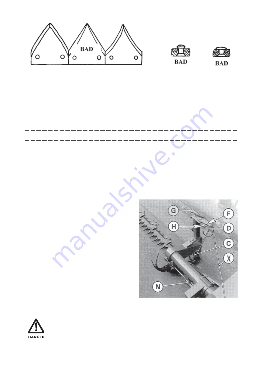
The FA 392 can be fitted with an optional hydraulic cylinder to raise and lower the cutterbar.
The hydraulic cylinder assembly (N) is fitted in place of
the manual lifting rod and the hydraulic hose is connected
to the tractor single acting outlet. Fit longer cord (X)
supplied with the kit. To do this, attach end of cord to stop
(C) and thread through the eyelet on latch (G) as shown in
the photo opposite.
To lower the cutterbar into the working position, proceed
as follows :
- Insert linchpin (D) in hole (H).
- Pull cord (X) to free latch (G).
- Operate valve on tractor hydraulics to release pressure.
Vertical transport position is obtained by pulling the cord
(X) to free stop (G) and by activating the tractor hydraulics
to raise the cutterbar. When the bar is in the vertical posi-
tion, it is automatically secured by latch (G) which hooks
around the back of the bar.
Next fit linchpin (D) in hole (F) provided for the transport and parking
position.
MAKE SURE THAT THE KNIFE GUARD IS ALWAYS IN PLACE WHEN TRANSPORTING, PARKING AND
STORING THE MACHINE.
WHEN CHANGING THE MACHINE FROM THE TRANSPORT TO THE WORK POSITION AND VICE
VERSA, THE PTO SHAFT MUST BE DISCONNECTED FROM THE TRACTOR PTO.
Summary of Contents for FA 392
Page 1: ...ASSEMBLY OPERATOR S MANUAL FA 392 REAR MOUNTED MOWER N 95007 A GB 12 95...
Page 11: ...9...
Page 12: ...10...
Page 13: ...11...
Page 26: ...N O T E S...