KUHN FA 392 Assembly & Operators Manual Download Page 20

- 18 -

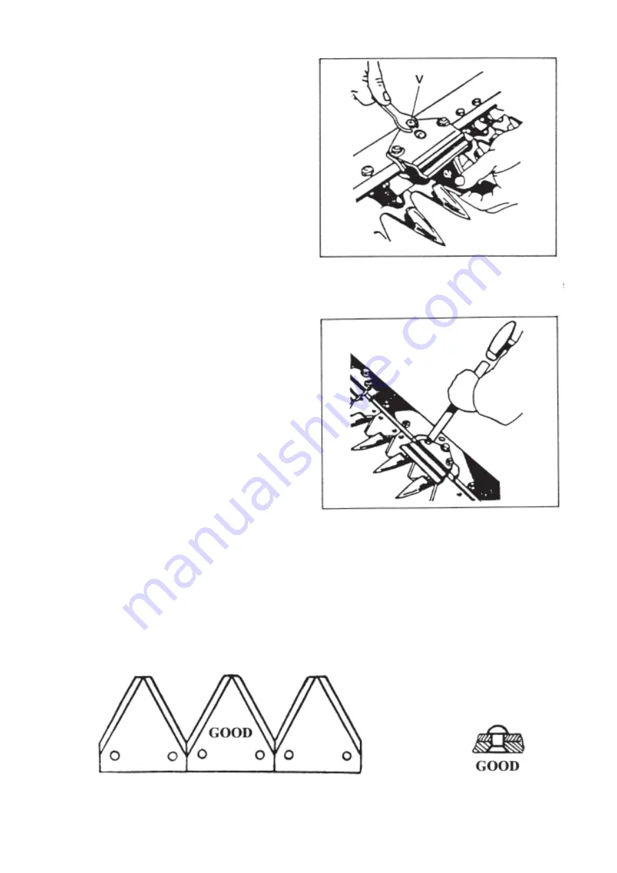
3) KNIFE CLIPS (3) must be correctly fitted over the

top of the raised section. Ensure they are not set at the
back or at the front only, for that would increase the
wear. Screw (V) can be adjusted to lower the knife
clip and give good support to the knife on the surface
of the finger (1). Carefully regulate screw (V) :
- to set all knive clips evenly,
- to avoid clamping the knife.

4) WINGS (4) guide the side of the knife and must contact each other without slack. They are used to line up the fingers

on their top side and back edge.

5)  WEAR PLATES (6) under the knife clips have ob-

long holes to adjust the side play on the blade. It is
advisable to set the play between the knife back and
the wear plates between  1 and 1.5 mm and to set all
the wear plates at the same level.

6)  KNIFE HEAD GUIDE : Excessive play is counteracted by removing shims located underneath the knife head guide.

7) THE KNIFE must always have well sharpened sections with an angle as near as possible to the original one. An angle

smaller than 20° gives a better cut, but makes the sections more easily jagged. An angle larger than 25° gives a bad cut.
The sections have been tempered to a width of 10 mm from the edge, so they should not be ground beyond this width
as the bevelling would not hold. When replacing a section, do not crush the rivets, for should they get compressed on
their whole length, they might distort or burst the edge. Ensure the knife is always straight and the sections well in line
with each other.

When replacing sections, study illustrations below :

When sharpening blades, always maintain the original angle.
Never rivet a section while the blade is in the cutterbar.

Summary of Contents for FA 392

Page 1: ...ASSEMBLY OPERATOR S MANUAL FA 392 REAR MOUNTED MOWER N 95007 A GB 12 95...

Page 2: ...instruct you on the general operation of your machine He is interested that you get the best performance possible and will be glad to answer any special questions that may arise regarding the operati...

Page 3: ...1 Lowering the cutterbar 12 2 Cutterbar lead adjustment 12 3 Cutterbar offsett adjustment 12 4 Lifting mechanism adjustment 13 5 Angle of cut adjustment 13 6 Belt tension adjustment 14 7 Forward spee...

Page 4: ...s at the risk and responsibility of the operator Designated use of the machine also means following operation maintenance and repair recommendations given by the manufacturer using only genuine spare...

Page 5: ...he machine risk of projection 8 Carrying people or animals on the machine when working or in transport is strictly forbidden 9 Machine must only be attached to tractor using means provided and in acco...

Page 6: ...ning or repairing the machine turn off the engine removeignition key and wait until all moving parts have come to a complete stop 27 Do not stand between the tractor and the machine unless the hand br...

Page 7: ...nto place 7 Make sure guards are correctly in place and secured with the safety chains provided 8 Before engaging PTO ensure that PTO speed and direction are in accordance with manufacturers recommend...

Page 8: ...t lower the machine depressurize the circuit turn off the engine and remove ignition key MAINTENANCE 1 Before checking any machine malfunction and before adjusting maintaining or repairing the machine...

Page 9: ...ojected It is therefore imperative that everyone be kept away from the danger zone that extra care is taken and that extra precaution such as safety indicators be taken when mowing pastures alongside...

Page 10: ...BEEN PLACED ON YOUR MACHINE IN THE AREAS INDICATED THEY ARE INTENDED FOR YOUR PERSONAL SAFETY AND FOR THE SAFETY OF THE PEOPLE WORKING WITH YOU THE TEXT SHOWN ON THEM GIVES THEIR PRECISE MEANING KEEP...

Page 11: ...9...

Page 12: ...10...

Page 13: ...11...

Page 14: ...r of 2 3 8 6 cm To ensure this posi tion is maintained the linkage arms of the tractor must be stabilised When measuring a 90 angle between the side of the tractor wheel and the cutterbar there must b...

Page 15: ...ow the horizontal Plate C limits the amount of angle raised to avoid damage to the pitman The total angle of movement of the cutterbar through 40 enables this to follow wide differences of ground con...

Page 16: ...with a forward speed of 6 4 km hr 4 mph and a PTO speed of 540 rpm This allows 9 10 revolutions of the final drive pulley for every 3 ft of travel Maintain the PTO speed and adjust tractor speed by ge...

Page 17: ...ncoupling from the tractor ALWAYS PARK THE MACHINE ON A FLAT HORIZONTAL SURFACE When transporting machine in the field swath board stick can be pivoted towards the front Fixation of swath board for tr...

Page 18: ...L MAINTENANCE Regularly check tightness of nuts and bolts Replace parts when they are worn Ensure knife sections are always sharp Follow the lubrication instructions carefully Check belt tension after...

Page 19: ...n sharp for longer and because of this they are harder than the guiding area As the central surface is not as hard as the bevelled edge after long and intense use the bevelled edges can become jagged...

Page 20: ...set all the wear plates at the same level 6 KNIFE HEAD GUIDE Excessive play is counteracted by removing shims located underneath the knife head guide 7 THE KNIFE must always have well sharpened sectio...

Page 21: ...angle adjustment 2 HYDRAULICCUTTERBARLIFT No 1006050 The FA 392 can be fitted with an optional hydraulic cylinder to raise and lower the cutterbar The hydraulic cylinder assembly N is fitted in place...

Page 22: ...aler will always be pleased to give you advice on our equipment He maintains a stock of KUHN parts to give you good vervice When ordering KUHN parts always state 1 Type of machine FA392 2 Serial numbe...

Page 23: ...ealth and Safety Executive The method employed corresponds to the method No 4 in this document Unspecified testing conditions comply with ISO 5131 standard Measuring equipment conforms to NF S 31 009...

Page 24: ...it has been misused neglected or damaged by accident or let out on hire Nor can claims be accepted if parts other than those manufactured by us have been incorporated in any of our equipment Furtherm...

Page 25: ...ions on all questions as to defect and to the exchange of any part or parts That all safety instructions in the Operator s Manual shall be followed and all safety guards regularly inspected and replac...

Page 26: ...N O T E S...

Page 27: ...tive The Operator should respect all Health and Safety regulations as well as the Highway Code For your own safety use only genuine KUHN spare parts The manufacturer disclaims all responsibilities due...

Page 28: ...abriques F 67706 SAVERNE CEDEX FRANCE T l 33 0 3 88 01 81 00 Fax 33 0 3 88 01 81 03 www kuhnsa com E mail info kuhnsa com Soci t Anonyme au Capital de 19 488 000 Euros For your safety and to get the b...

Reviews: