background image

Dr Walt’s Quick Guide to Keycreator Sheet Metal Tools- Part 1 

 
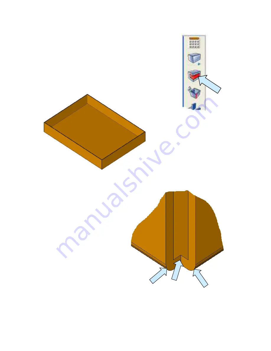
Next, click on the SHELL Icon. 
 
When the Dialog Box appears, type “t” for the shell thickness. 
Use the Select Faces to be Opened Option  and click on the 
OK Button. 
 
Then, select the top surface of the block. 


When the shelling operation is 
completed, your part should look 
like this: 


Now what we have is fine as a 
conceptual model of the part. 
However, it does not represent a sheet 
metal fabricated part for two reasons.  
 
First, the bends at the bottom edges are 
not sheet metal bends and second, the 
corners are closed as though it were 
molded from a piece of plastic. 
 
I’ve illustrated what we want to 
achieve in the enlarged view to the 
right. (Note: In actual practice we use 
a much smaller corner rip. I’ve made 
this one large so you can see what is 
going on.) 


Summary of Contents for KeyCreator

Page 1: ...Dr Walt s Quick Guide to Keycreator Sheet Metal Tools Part 1 1...

Page 2: ...ith creating a custom toolbar I recommend that you use my Tips and Tricks exercise on creating hot keys and toolbars or one of my books like Doctor Walt s Keycreator Workbook The first tool on the too...

Page 3: ...BEND CORNER Tool Next I place the CREATE FLANGE Icon then the ADD SHEETMETAL BEND and then the CREATE BEND RELIEF Icon Next drag the EDIT SHEETMETAL BEND and UNBEND ALL Icons onto the toolbar Let s a...

Page 4: ...a different collection of Icons You might argue that functions like the EXTRUDE FACE and ONLINE CALCULATOR don t belong on this toolbar since they are not purely specifically sheet metal tools My pur...

Page 5: ...sign a value of 0 032 as the sheet metal thickness in this file Next click on the BLOCK Icon A Dialog Box appears Use the Key In Option and type 8 for the width 6 for the length and 1 for the height U...

Page 6: ...your part should look like this Now what we have is fine as a conceptual model of the part However it does not represent a sheet metal fabricated part for two reasons First the bends at the bottom edg...

Page 7: ...rtical corners Don t worry about whether you are picking the inner or outer corner It doesn t matter Your part will now have ripped corners that look like this Our next step is to fix the four bottom...

Page 8: ...n each of the bottom corners on the part Again don t worry about inner versus outer edge Keycreator is smart enough to know what you want The bottom of your part will now have true sheet metal bends N...

Page 9: ...m Click on the broad inside surface of the part The flat development is created on the screen You can click on the UNDO Icon to revert to the folded part This ends Part 1 of our exercise In an upcomin...

Reviews: