Kubota DF972-E2 Workshop Manual Download Page 130

S-60

WG972-E2, DF972-E2, WSM

GASOLINE / LPG ENGINE

(4) Crankshaft

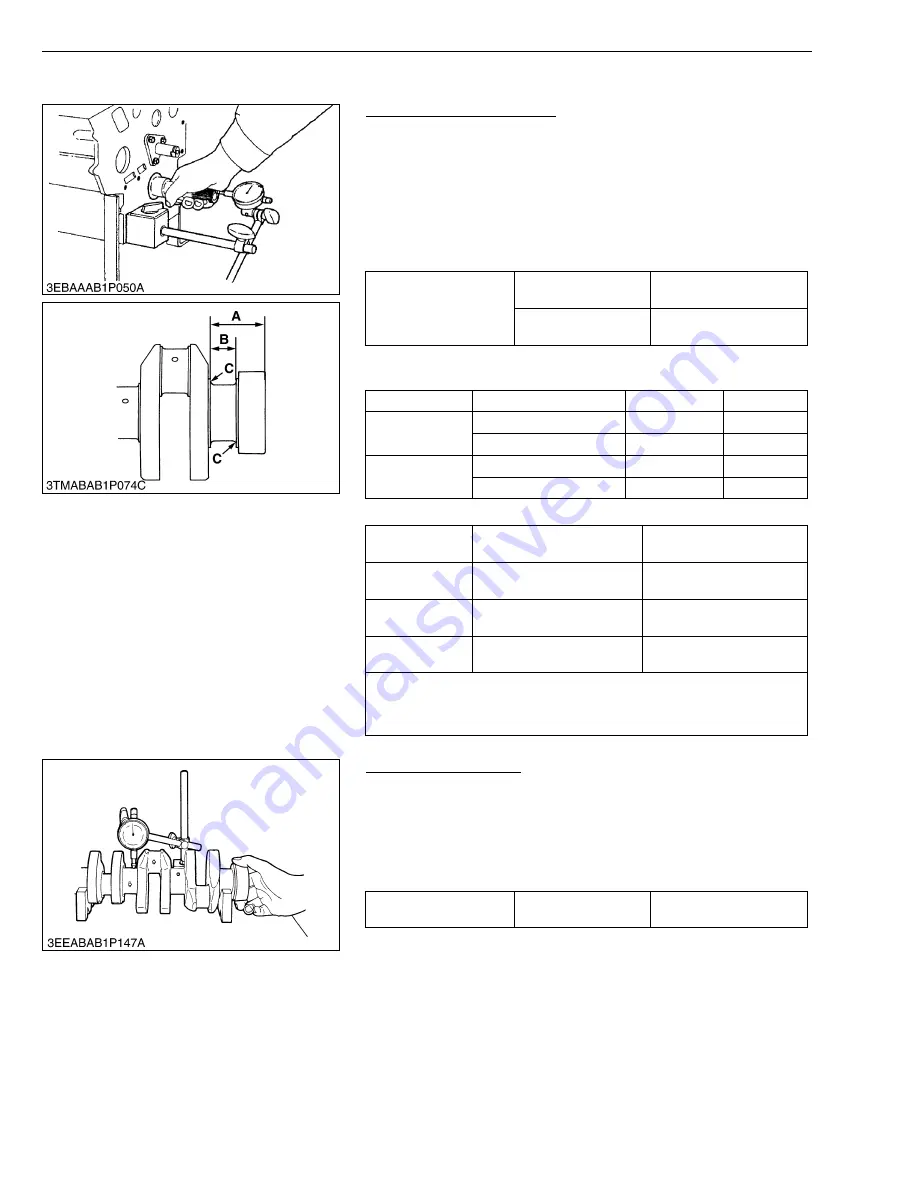
Crankshaft Side Clearance

1. Set a dial indicator with its tip on the end of the crankshaft.
2. Measure the side clearance by moving the crankshaft to the front

and rear.

3. If  the  measurement  exceeds  the  allowable  limit,  replace  the

thrust bearings.

4. If  the  same  size  bearing  is  useless  because  of  the  crankshaft

journal wear, replace it with an oversize one referring to the table
and figure.

(Reference)

• Oversize thrust bearing

• Oversize dimensions of crankshaft journal

W1066738

Crankshaft Alignment

1. Support the crankshaft with V blocks on the surface plate at both

end journals.

2. Set a dial indicator with its tip on the intermediate journal.
3. Measure the crankshaft alignment.
4. If  the  measurement  exceeds  the  allowable  limit,  replace  the

crankshaft.

W1067285

Crankshaft side 
clearance

Factory spec.

0.15 to 0.31 mm
0.0059 to 0.0122 in.

Allowable limit

0.50 mm
0.0197 in.

Oversize

Bearing

Code Number

Marking

0.2 mm
0.008 in.

Thrust bearing 1 02

15261-23950

020 OS

Thrust bearing 2 02

15261-23970

020 OS

0.4 mm
0.016 in.

Thrust bearing 1 04

15261-23960

040 OS

Thrust bearing 2 04

15261-23980

040 OS

Oversize

0.2 mm 

0.008 in.

0.4 mm

 0.016 in.

Dimension 

A

46.1 to 46.3 mm

1.815 to 1.823 in.

46.3 to 46.5 mm

1.823 to 1.831 in.

Dimension 

B

23.40 to 23.45 mm

0.9134 to 0.9154 in.

23.80 to 23.85 mm

0.9213 to 0.9232 in.

Dimension 

C

1.8 to 2.2 mm radius

0.071 to 0.087 in. radius

1.8 to 2.2 mm radius

0.071 to 0.087 in. radius

                                                                                            (0.8S)
The crankshaft journal must be fine-finished to higher than 

∇∇∇∇

.

*Holes to be de-burred and edges rounded with 1.0 to 1.5 mm
 (0.0394 to 0.0591 in.) relief.

Crankshaft alignment

Allowable limit

0.02 mm
0.0008 in.

KiSC issued 01, 2006 A

Summary of Contents for DF972-E2

Page 1: ...WORKSHOP MANUAL GASOLINE LPG ENGINE WG972 E2 DF972 E2 KiSC issued 01 2006 A...

Page 2: ...cluded This part should be understood before proceeding with troubleshooting disassembling and servicing Servicing There are troubleshooting servicing specification lists checking and adjusting disass...

Page 3: ...is manual and on labels on the machine itself to warm of the possibility of personal injury Read these instructions carefully It is essential that you read the instructions and safety regulations befo...

Page 4: ...jack Always support the machine by safety stands Do not touch the rotating or hot parts while the engine is running Never remove the radiator cap while the engine is running or immediately after stop...

Page 5: ...yes Keep electrolyte away from eyes hands and clothing If you spill electrolyte on yourself flush with water and get medical attention immediately DISPOSE OF FLUIDS PROPERLY Do not pour fluids into th...

Page 6: ...it is applied for EPA and CARB certified engines only EPA and CARB emission regulations require the ultimate user of non road SI engine as their obligation to adjust the emissions by installing the ap...

Page 7: ...ommercial Propane gas only Equivalent to Propanes H D 5 of GPA standards vol C3H8 C3H6 C4H10 Others 90 5 2 5 5 LENGTH OF THE LPG VAPOR HOSE DF972 E2 The length of the LPG vapor hose between the LPG ca...

Page 8: ...to 3950 min 1 rpm Minimum Bare Idling Speed 1400 to 1600 min 1 rpm Cylinder Head Overhead Valve Ignition System Distributor Less Solid Stage Type Governor Centrifugal Ball Mechanical Type Electronic...

Page 9: ...TIONS GPA means Gas Processors Association U S A W1032351 KUBOTA RECOMMENDED LPG FUEL SPECIFICATIONS Commercial Propane gas only Equivalent to Propanes H D 5 of GPA standards vol C3H8 C3H6 C4H10 Other...

Page 10: ...epower 2 Engine Speed 3 Specific Fuel Consumption 4 Torque 5 Net Intermittent Torque 6 Net Continuous Torque 7 Net Intermittent Brake Horsepower 8 Net Continuous Brake Horsepower 9 Net Intermittent Sp...

Page 11: ...9 WG972 E2 DF972 E2 WSM DIMENSIONS DIMENSIONS KiSC issued 01 2006 A...

Page 12: ...10 WG972 E2 DF972 E2 WSM DIMENSIONS Electronic Governor Model KiSC issued 01 2006 A...

Page 13: ...witch Relay Driver Power Input Gasoline Solenoid Valve Cavbuleter Fuel Pump Pilot Box Assy Starter Battery Fuse Charge Lamp Water Temp Lamp Oil Fuse Starter Switch 50 30 19 AC 50 30 19 AC 17 30 19 50...

Page 14: ...4 CHECK AND MAINTENANCE G 6 1 DAILY CHECK POINTS G 6 2 CHECK POINTS OF INITIAL 50 HOURS G 8 3 CHECK POINTS OF EVERY 50 HOURS G 9 4 CHECK POINTS OF EVERY 100 HOURS G 10 5 CHECK POINTS OF EVERY 200 HOU...

Page 15: ...umber The engine serial number is an identified number for the engine It is marked after the engine model number It indicates month and year of manufacture as follows Year of manufacture W1010477 Alph...

Page 16: ...ad cover of the engine certified to the requirements of EPA CARB Emission regulations The content of the label is approved officially by EPA CARB W1025355 Month Engine Serial Number 0001 9999 10000 Ja...

Page 17: ...ssion Regulations through its useful life Intentional removal and adjustment of such tamper resistance are subject to the penalty W1025903 2 CYLINDER NUMBER The cylinder numbers of KUBOTA gasoline LPG...

Page 18: ...battery first Remove oil and dirt from parts before measuring Use only KUBOTA genuine parts for parts replacement to maintain engine performance and to ensure safety Gaskets and O rings must be replac...

Page 19: ...G fuel hose and clamp bands Cleaning air cleaner element Checking battery electrolyte level Checking spark plug Cleaning fuel filter Check fan belt tension and damage Replacing oil filter cartridge Ch...

Page 20: ...e drain old oil Never mix two different types of oil IMPORTANT Use the proper SAE Engine oil according to ambient temperatures NOTE Be sure to inspect the engine locating it on a horizontal place If p...

Page 21: ...ot remove the radiator cap until coolant temperature is below its boiling point Then loosen the cap slightly to relieve any excess pressure before removing the cap completely IMPORTANT During filling...

Page 22: ...line hoses and clamps W1031214 2 CHECK POINTS OF INITIAL 50 HOURS Changing Engine Oil CAUTION Be sure to stop engine before changing engine oil 1 Start and warm up the engine for approx 5 minutes 2 P...

Page 23: ...05 kPa 2 1 kgf cm2 30 psi 2 If the element is stained with carbon or oil replace the element IMPORTANT Make sure the wing bolt for the element is tight enough If it is loose dust and dirt may be sucke...

Page 24: ...N Never remove the vent plugs while the engine is running Keep electrolyte away from eyes hands and clothes If you are spattered with it wash it away completely with water immediately and get medical...

Page 25: ...ween the fan drive pulley and alternator pulley at specified force 98 N 10 kgf 22 lbs 2 If the measurement is not within the factory specifications loosen the alternator mounting screws and relocate t...

Page 26: ...ter cartridge 1 with the filter wrench 2 Apply a slight coart of oil onto the new cartridge gasket 3 To install the new cartridge screw it in by hand Over tightening may cause deformation of rubber ga...

Page 27: ...ery 200 hours of operation or every six months whichever comes first 2 If the clamp is loose apply oil to the threads and retighten it securely 3 The water hose is made of rubber and tends to age It m...

Page 28: ...hose is damaged replace it W1055412 Draining Tar Vaporizer for DF972 E2 1 Run the engine until it is warmed up 2 The shut off valve is shut and the engine is stopped naturally 3 Place an oil pan unde...

Page 29: ...rear end plate so that the No 1 piston comes to the overlap position 6 Check the following valve clearance marked with using a feeler gauge 7 If the clearance is not within the factory specifications...

Page 30: ...eplacing the Air Cleaner Element 1 Remove the dust cup from the air cleaner 2 After cleaning the dust cup remove the air cleaner element 3 Replace the new air cleaner element W1018144 Replacing Fuel F...

Page 31: ...instruction 6 After flushing fill with clean water and anti freeze until the coolant level is just below the port Install the radiator cap 1 securely 7 Fill with coolant up to FULL A mark on the reco...

Page 32: ...ic A higher boiling point is obtained by using a radiator pressure cap which permits the development of pressure within the cooling system NOTE The above data represents industrial standards that nece...

Page 33: ...he fuel hose and the clamps LPG line W10403890 Replacing the Hot Water Hoses 1 Coonnect the water hose 1 and 2 through the vaporizer 2 The water joint part of vaporizer is adjusted to the upper side A...

Page 34: ...factory specification replace the vaporizer W1024942 Checking Air Tight of Secondary Chamber Vaporizer for LPG Fuel 1 Disconnect the vapor hose 1 on the mixer side 2 Breath is blown lightly or compre...

Page 35: ...excess pressure before removing cap completely 1 Drain the coolant 2 Loosen the clamp bands 3 Remove the upper hose 1 and lower hose 2 4 Replace new upper lower hose 1 2 and clamp bands 5 Tighten the...

Page 36: ...Tester Code No 07916 32032 Application Use to measure lubricating oil pressure W1043015 Radiator Tester Code No 07909 31551 Application Use to check of radiator cap pressure and leaks from cooling sy...

Page 37: ...in H 6 0 to 6 1 mm dia 0 236 to 0 240 in dia I 5 mm 0 197 in J 18 mm dia 0 71 in dia K 10 6 to 10 7 mm dia 0 417 to 0 421 in dia L 7 mm 0 276 in C1 Chamfer 1 0 mm 0 039 in C2 Chamfer 2 0 mm 0 079 in C...

Page 38: ...dia 1 7283 to 1 7303 in dia A 130 mm 5 12 in B 72 mm 2 83 in C 40 mm radius 1 57 in radius D 9 mm 0 35 in E 24 mm 0 95 in F 20 mm 0 79 in G 68 mm dia 2 68 in dia H 43 90 to 43 95 mm dia 1 7283 to 1 7...

Page 39: ...al communications port and Windows 95 98 2000 NT Me XP as the operating system Datalink harness A connectivity kit Woodward No 8923 1061 can be purchased from Woodward to accomplish this In addition t...

Page 40: ...IDGE M 9 5 OIL PRESSURE SWITCH M 10 4 COOLING SYSTEM M 11 1 GENERAL M 11 2 COOLING FIN M 11 3 WATER PUMP M 11 4 THERMOSTAT M 12 5 RADIATOR M 12 6 RADIATOR CAP M 13 7 VAPORIZER DF972 E2 M 13 5 FUEL SYS...

Page 41: ...and a special SI combustion chamber To simplify maintenance most engine parts are interchangeable with their diesel counterparts The new WG DF engines will meet and beat the toughest industrial chall...

Page 42: ...is reduced to a minimum because each cylinder has its own chamber To increase the rigidity of the cylinder block parts of engine block which support main bearing case has thicker rib for additional r...

Page 43: ...l heat resistant stellite alloys W11094950 4 CRANKSHAFT The crankshaft with the connecting rod converts the reciprocating motion of the piston into rotating motion The crankshaft 2 has oil passages dr...

Page 44: ...nt abnormal wear due to edge loading at the time of initial running in and it is very effective in prevention of blow by Oil Ring Oil ring consists of three steel components that is upper and lower ra...

Page 45: ...nkpin bearing 3 split type and the small end has a small end bushing 1 solid type 8 CAMSHAFT The camshaft 1 is made of special cast iron and the journal and cam sections are chilled to resist wear The...

Page 46: ...exhaust valves to open and close them 11 INLET AND EXHAUST VALVES The valve and its guide for the inlet are different from those for the exhaust Other parts such as the spring 4 spring retainer 3 col...

Page 47: ...l injection timing and top dead center The flywheel has gear teeth around its outer rim which mesh with the drive pinion of the starter 13 CLOSED BREATHER Blow by gas 1 from crankcase is deoiled in th...

Page 48: ...ed oil is forced to the crankshaft the connecting rods the idle gear the camshaft and the rocker arm shaft through the oil passage in the cylinder block and the shafts to lubricate the bearings Some o...

Page 49: ...elief valve is a ball direct acting type and is best suited for low pressures When the pressure of the oil forced by the pump exceeds the specified value the oil pushes back the ball 2 and escapes to...

Page 50: ...is led to the lubricating oil passage When the oil pressure falls below the specified value the oil pressure warning lamp lights 1 Terminal 2 Insulator 3 Spring 4 Rubber Gasket 5 Contact Rivet 6 Cont...

Page 51: ...or only to the water pump while closed W1013684 2 COOLING FIN The cooling fin is set up around the oil passage in the gear case Therefore the temperature of oil is decreased by the wind generated by...

Page 52: ...or Only the air in the water jacket escapes to the radiator through the leak hole 8 of the thermostat At high temperature higher than 85 C As the coolant temperature rises the wax in the pellet 3 turn...

Page 53: ...e internal pressure When the coolant temperature falls and a vacuum forms in the radiator the vacuum valve 2 opens to introduce the air into the radiator 7 VAPORIZER DF972 E2 When evaporating by prima...

Page 54: ...in vaporizer and is sent to the DF Carburetor 7 as a gaseous fuel of gas pressure near the atmospheric pressure The DF carburetor 7 mixes the gas and air is supplied in the cylinder 1 Gasoline Tank 2...

Page 55: ...in the inner wall This causes gasoline in the main nozzle 6 to flow through the pilot jet 24 to be sucked into the cylinder Air that enters from the pilot air jet 25 is mixed with gasoline in the pilo...

Page 56: ...el flows to the mixing chamber The mixer meters both fuel and air and procedures an air fuel mixture that has the proper ratio as required by the engine When the engine starts the LPG furl flows out f...

Page 57: ...s more than the specified pressure 32 7 kPa 0 3 kgf cm2 4 3 psi the tension in the diaphragm spring 3 is overcome and do the push up of primary diaphragm 4 At this time do the push up of primary valve...

Page 58: ...a secondary valve spring When the engine rotates the negative pressure is generated in the venturi tube of the mixer As for this negative pressure working secondary diaphragm 8 is pulled to the second...

Page 59: ...re is caused in inlet manifold at the same time as the cranking s beginning This negative pressure acts in vacuum lock chamber 3 and vacuum lock diaphragm 5 is drawn to the vacuum lock chamber side As...

Page 60: ...ork lever 7 governor lever shaft 3 and governor lever 2 The engine speed and output are thus kept constant 2 When load is applied to engine When the load is applied to the engine running at rated spee...

Page 61: ...hrough the filter element 1 the dirt and impurities in the fuel are filtered allowing only clean fuel to penetrate the inside of the filter element The cleaned fuel flows out from the outlet B 8 ELECT...

Page 62: ...current flowing to the ignition coil 5 is also controlled In this way a high voltage is generated at the secondary winding of the ignition coil 5 which activates the spark plug 6 Without any mechanica...

Page 63: ...The engine starts and increases its speed While the pinion spins faster than the armature the overrunning clutch 7 allows the pinion to spin independently from the armature The pull in coil 4 is shor...

Page 64: ...battery At any position of the key except the OFF position the terminal AC is connected to the 30 terminal 30 from battery AC to regulator oil lamp and accessory W1017536 2 CHARGING SYSTEM Alternator...

Page 65: ...tor series system 2 Built in AC diode generation detecting circuit permits a charge indication lamp 12 V 3 4 W to be easily connected 3 Protection diode protects regulator when battery is wrongly conn...

Page 66: ...ter starts engine GEN also starts generation for charging and LAMP is turned off In detail with GEN starting current flows to base of Q1 through the route of GEN D1 emitter base of Q1 R4 D4 GEN or GEN...

Page 67: ...rge current is supplied to BATT through the route of GEN D1 BATT anode cathode of S2 GEN or GEN D2 BATT anode cathode of S1 GEN After S1 or S2 is turned on collector current of Q1 and base current of...

Page 68: ...lows to the solenoid which in turn opens the solenoid valve When the key switch is turned off the solenoid valve closes blocking the gasoline main jet 2 LPG main jet 4 W1037289 1 Gasoline Solenoid Val...

Page 69: ...ith integrated speed control software to control the speed of the engine Electronic governor is a microprocessor based control that is incorporated into the actuator creating a single integrated packa...

Page 70: ...ting System S 17 3 Cooling System S 17 4 Fuel System S 20 5 Ignition System S 24 6 Electrical System S 27 7 Electronic Governor S 31 2 DISASSEMBLING AND ASSEMBLING S 32 1 Draining Coolant and Engine O...

Page 71: ...er valve clearance Adjust S 16 Defective ignition coil Replace S 25 Defective spark plug Adjust spark plug gap or replace G 10 Defective ignitor Replace S 26 Defective fuel system Check fuel line and...

Page 72: ...Spark knock due to low octane fuel or carbon Use higher octane fuel and remove carbon Rattles from loosely mounted external components Retighten Symptom Probable Cause Solution Reference Page Engine...

Page 73: ...G ENGINE 3 FOR ELECTRONIC GOVERNOR NOTE This troubleshooting describe the procedure which does not use the service tool soft wear Engine does not start Step 1 1 Refer to Adjust Governor Lever of Elect...

Page 74: ...2 WSM GASOLINE LPG ENGINE Engine does not start Step 2 1 Refer to the Air Gap of Engine Speed Sensor for Electronic Governor 2 Refer to the Resistance of Engine Speed Sensor for Electronic Governor Ki...

Page 75: ...S 5 WG972 E2 DF972 E2 WSM GASOLINE LPG ENGINE Engine unstable 1 Refer to the Adjust Governor Lever of Electronic Governor KiSC issued 01 2006 A...

Page 76: ...m 0 0020 in Valve Recessing Intake and Exhaust 0 10 to 0 10 mm 0 0039 to 0 0039 in 0 30 mm 0 0118 in Valve Stem to Valve Guide Valve Stem Valve Guide Clearance O D I D 0 030 to 0 057 mm 0 00118 to 0 0...

Page 77: ...de Bore Oil Clearance O D I D 0 016 to 0 052 mm 0 00063 to 0 00205 in 17 966 to 17 984 mm 0 70732 to 0 70803 in 18 000 to 18 018 mm 0 70866 to 0 70937 in 0 10 mm 0 0039 in Timing Gear Crank Gear to Id...

Page 78: ...arance O D I D 0 014 to 0 038 mm 0 00055 to 0 00150 in 20 002 to 20 011 mm 0 78748 to 0 78783 in 20 025 to 20 040 mm 0 78839 to 0 78897 in 0 10 mm 0 0039 in Piston Pin to Small End Bushing Spare Parts...

Page 79: ...in 0 20 mm 0 0079 in Crankshaft Journal to Crankshaft Bearing 2 Flywheel Side Crankshaft Journal Crankshaft Bearing 2 Oil Clearance O D I D 0 028 to 0 059 mm 0 00110 to 0 00232 in 43 934 to 43 950 mm...

Page 80: ...00531 in Item Factory Specification Allowable Limit Fan Belt Tension 7 0 to 9 0 mm 98 N 0 28 to 0 35 in 98 N 10 kgf 22 lbs Thermostat Valve Opening Temperature At Beginning Valve Opening Temperature...

Page 81: ...o 0 031 in 17 0 mm 0 669 in 31 0 mm 1 220 in 0 4 mm 0 016 in 0 2 mm 0 008 in 11 5 mm 0 453 in Alternator No load Output Voltage AC 20 V or more at 5200 min 1 rpm Regulator Regulating Voltage 14 to 15...

Page 82: ...ear mounting screw M6 x 1 9 8 to 11 3 1 00 to 1 15 7 2 to 8 3 Connecting rod screw M7 x 0 75 26 5 to 30 4 2 7 to 3 1 19 5 to 22 4 Flywheel screw M10 x 1 25 53 9 to 58 8 5 5 to 6 0 39 8 to 43 4 Bearing...

Page 83: ...W1012705 Grade Nominal Unit Diameter Standard Screw and Bolt Special Screw and Bolt N m kgf m ft lbs N m kgf m ft lbs M6 7 9 to 9 3 0 80 to 0 95 5 8 to 6 9 9 8 to 11 3 1 00 to 1 15 7 23 to 8 32 M8 17...

Page 84: ...rement is below the allowable limit apply a small amount of oil to the cylinder wall through the spark plug hole and measure the compression pressure again 8 If the compression pressure is still less...

Page 85: ...ead screws to the specified torque 4 Turn the flywheel until the piston exceeds top dead center 5 Remove the cylinder head and measure the thickness of the squeezed fuses 6 If the measurement is not w...

Page 86: ...the rear end plate so that the No 1 piston comes to the overlap position 6 Check the following valve clearance marked with using a feeler gauge 7 If the clearance is not within the factory specificat...

Page 87: ...engine oil pressure switch to the specified torque W10349520 3 Cooling System Fan Belt Tension 1 Measure the deflection A depressing the belt halfway between the fan drive pulley and alternator pulley...

Page 88: ...thermostat in the water by a string with its end inserted between the valve and seat 2 Heating the water gradually read the temperature when the valve opens and leaves the string 3 Continue heating an...

Page 89: ...ry specification replace the radiator cap W1054156 Radiator Water Leakage 1 Pour a specified amount of water into the radiator 2 Set a radiator tester 1 and an adapter 2 and raise the water pressure t...

Page 90: ...with the throttle adjust screw 2 to 1200 min 1 rpm 1100 to 1300 min 1 rpm 4 Adjust the low idling speed adjust screw 4 until the engine speed reaches 1500 min 1 rpm 1400 to 1600 min 1 rpm with the spe...

Page 91: ...or 11 Adjust the engine speed NOTE After install the carburetor the adjustment of governor and engine speed are executed Prepare a screwdriver that fits the main jet pilot jet screws in order not to d...

Page 92: ...can be adjusted to any position The joint must be tight in that position Apply an approved for GAS or LPG use liquid gasket Three Bond 1104 or its equivalent to thread see figure and tighten it Drain...

Page 93: ...fittings piping should be approved for LPG use and conform to UL CSA NFPA and all other recognized standards An approved listed fuel filter and electromechanical positive shutoff must be installed be...

Page 94: ...tant 5 the ignition timing adjustment screw has been covered after adjustment at the factory W1103663 Resistance of Pick Up Sensor 1 Disconnect the connector 2 Measure the resistance with an ohmmeter...

Page 95: ...Measure the air gap with a feeler gauge 2 If air gap differs from the factory specification readust the air gap NOTE The described numerical value is the values of KBT parts Checking sensor as describ...

Page 96: ...o 40 k 10 to 40 k 11 to 47 k infinity infinity infinity infinity B 10 to 40 k 0 33 to 1 3 k 1 8 to 7 3 k infinity infinity infinity infinity C 10 to 40 k 0 33 to 1 3 k 1 5 to 6 0 k infinity infinity i...

Page 97: ...or to the magnet switch W1024938 Magnetic Switch Test 1 Disconnect the battery negative cable from the battery 2 Disconnect the battery positive cable from the battery 3 Disconnect the leads from the...

Page 98: ...gnet switch W1024940 No load Dynamo Output 1 Disconnect the lead wires from the dynamo 2 Start the engine and operate the dynamo at the specified speed 3 Measure the output voltage with a volt meter I...

Page 99: ...he unit for the measuring range The judgement should be as below table ON if the indicator moves otherwise OFF Check Table ON OFF W1021509 Regulating Voltage 1 Complete the charging circuit with a ful...

Page 100: ...between 13 8 V and 14 8 V the alternator is operating normally 3 If the results of alternator on unit test are not within the specifications disassemble the alternator and check the each component par...

Page 101: ...nning the engine because the electronic governor dos not operate The adjustment of the idle speed due to this process is not an adjustment of the final product 1 Disconnect actuator connector 1 2 Star...

Page 102: ...ine for approx 5 minutes 2 Place an oil pan underneath the engine 3 Remove the drain plug 1 to drain oil 4 After draining screw in the drain plug When refilling Fill the engine oil up to the upper lin...

Page 103: ...sconnect the gasoline hose from the connector 1 W1125277 LPG Hose and Water Hose DF972 E2 CAUTION Vent the air of the water passage of vaporizer 5 after detaching the water hose 2 1 Disconnect the LPG...

Page 104: ...overnor lever nut 3 Remove the governor lever 7 with governor rod 5 and governor spring 6 4 Disconnect the breather hose 3 5 Remove the air cleaner flange 2 and air cleaner gasket 6 Remove the carbure...

Page 105: ...2 by finger in the direction of the engine speed reduction so as not to overrun The adjustment of the idle speed due to this process is not an adjustment of the final product 1 Disconnect the connecto...

Page 106: ...e valve to the fully OPEN position with the governor lever 3 turn the groove on the governor lever shaft 5 fully clockwise with a screwdriver to open the governor completely and then tighten the nut 6...

Page 107: ...er Head Valves and Oil Pan Cylinder Head Cover 1 Remove the head cover screws 1 2 Remove the cylinder head cover 2 3 Remove the intake manifold 3 When reassembling Check to see if the cylinder head co...

Page 108: ...the cylinder head screws after applying sufficient oil Tighten the cylinder head screws in order of a to n Tighten them uniformly or the head may deform in the long run W1025645 Tappets 1 Remove the t...

Page 109: ...e proper fit with a plastic hammer Install a new stem seal on the valve guide 10 vertically with a jig 9 when insert the stem seal 6 See page G 24 Valve Stem Seal Replacing Tool IMPORTANT Be sure stem...

Page 110: ...0 20 in thick all over the contact surface Apply the adhesive also on the center of the flange as well as on the inner wall of each bolt hole Cut the nozzle of the liquid gasket Three Bond 1207D or e...

Page 111: ...crew 3 Draw out the fan drive pulley with a puller When reassembling Install the pulley to the crankshaft aligning the mark 1 on them Apply engine oil to the fan drive pulley retaining screws And tigh...

Page 112: ...l the idle gear aligning the mark 6 on the gears referring to the photo W1030437 Camshaft 1 Remove the camshaft mounting screws 1 and draw out the camshaft with gear 2 on it When reassembling When ins...

Page 113: ...ting Rod Connecting Rod Cap 1 Remove the connecting rod caps 1 using a bihexagonal 8 mm socket When reassembling Align the marks a with each other Face the marks toward the intake manifold Apply engin...

Page 114: ...r the gaps A E of the second compression ring and spacer making 2 09 rad 120 from the gap of the top compression ring Further stagger the gaps D B of the upper and lower side rail making 1 57 rad 90 f...

Page 115: ...PORTANT Mark the same number on the connecting rod and the piston so as not to change the combination W10281670 7 Crankshaft Flywheel 1 Secure the flywheel to keep it from turning using a flywheel sto...

Page 116: ...o position the casting mark UP a on it upward Apply engine oil to the oil seal 5 lip and take care that it is not rolled when installing Tighten the bearing case cover mounting screws with even force...

Page 117: ...he third cylinder 4 Repeat the above steps to draw out all the crankshaft When reassembling Clean the oil passage of the crankshaft with compressed air Install the crankshaft assembly aligning the scr...

Page 118: ...bearing 3 5 9 Install the bearing with the oil groove c up Match the alignment numbers a on the main bearing case assembly 1 Do the same for the main bearing case assembly 2 2 and the main bearing ca...

Page 119: ...out the armature 9 with the drive lever 3 NOTE Do not damege to the brush and commutator When reassembling Apply grease DENSO CO LTD No 50 or its equivalent to the parts indicated in the figure Joint...

Page 120: ...e recessing after correcting W1061323 Cylinder Head Flaw 1 Prepare an air spray red check 2 Clean the surface of the cylinder head with the detergent 2 3 Spray the cylinder head surface with the red p...

Page 121: ...e valve guide I D with a small hole gauge and calculate the clearance 4 If the clearance exceeds the allowable limit replace the valves If it still exceeds the allowable limit replace the valve guide...

Page 122: ...ng replacement W10314690 Valve Seating 1 Coat the valve face lightly with prussian blue and put the valve on its seat to check the contact 2 If the valve does not seat all the way around the valve sea...

Page 123: ...a 0 785 rad 45 valve seat cutter again and visually recheck the contact between the valve and seat 5 Repeat steps 3 and 4 until the correct contact is achieved 6 Continue lapping until the seated rate...

Page 124: ...70 Oil Clearance between Rocker Arm and Rocker Arm Shaft 1 Measure the rocker arm shaft O D with an outside micrometer 2 Measure the rocker arm I D with an inside micrometer and then calculate the oil...

Page 125: ...hafts and the gear 4 If the oil clearance is proper replace the gear W1064048 Push rod alignment Allowable limit 0 25 mm 0 0098 in Oil clearance between tappet and tappet guide bore Factory spec 0 016...

Page 126: ...n the surface plate at both end journals 2 Set a dial indicator with its tip on the intermediate journal 3 Measure the camshaft alignment 4 If the measurement exceeds the allowable limit replace the c...

Page 127: ...ut the used idle gear bushing using an idle gear bushing replacing tool When installing 1 Clean a new idle gear bushing and idle gear bore and apply engine oil to them 2 Press in a new bushing using a...

Page 128: ...nstalling 1 Clean a new small end bushing and bore and apply engine oil to them 2 Using a small end bushig replacing tool press in a new bushing service parts taking due care to see that the connectin...

Page 129: ...the connecting rod 3 Install the connecting rod on the connecting rod alignment tool 4 Put a gauge over the piston pin and move it against the face plate 5 If the gauge does not fit squarely against t...

Page 130: ...asurement exceeds the allowable limit replace the crankshaft W1067285 Crankshaft side clearance Factory spec 0 15 to 0 31 mm 0 0059 to 0 0122 in Allowable limit 0 50 mm 0 0197 in Oversize Bearing Code...

Page 131: ...dimensions of crankpin W11625390 Oil clearance between crankpin and crankpin bearing Factory spec 0 020 to 0 051mm 0 00079 to 0 00201 in Allowable limit 0 15 mm 0 0059 in Crankpin O D Factory spec 33...

Page 132: ...e exhaust manifold side See figure W10342000 Oil Clearance between crankshaft journal and crankshaft bearing 1 Factory spec 0 034 to 0 106 mm 0 00134 to 0 00417 in Allowable limit 0 20 mm 0 0079 in Cr...

Page 133: ...ecause of the crankshaft journal wear replace it with an undersize one referring to the table and figure NOTE Be sure not to move the crankshaft while the bearing case screws are tightened W10344030 O...

Page 134: ...4 mm 0 016 in Crankshaft bearing 2 04 15694 23940 040 US Crankshaft bearing 2F 04 1G460 07540 Crankshaft bearing 3 04 1G460 07590 040 US Crankshaft bearing 3F 04 1G460 07640 Undersize 0 2 mm 0 008 in...

Page 135: ...s gauge 2 If the clearance exceeds the factory specifications replace the oil pump rotor assembly W10381420 Clearance between Rotor and Cover 1 Put a strip of plastigage onto the rotor face with greas...

Page 136: ...e of the O D s exceeds the allowable limit correct the commutator on a lathe to the factory specification 5 Measure the mica undercut 6 If the undercut is less than the allowable limit correct if with...

Page 137: ...h an ohmmeter 2 If it conducts replace the armature 3 Check the continuity across the segments of the commutator with an ohmmeter 4 If it does not conduct replace the armature W1075693 Field Coil 1 Ch...

Page 138: ...HINERY SERVICE LTD 64 ISHIZU KITAMACHI SAKAI CITY OSAKA 590 0823 JAPAN PHONE 81 72 241 1129 FAX 81 72 245 2484 E mail ksos pub kubota co jp KUBOTA Corporation Printed in Japan 2006 01 S EI E I e Code...

Reviews: