


SKY PRO 1800 FORCED CIRCULATION MANUAL
C
C
C
16
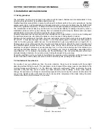
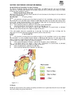
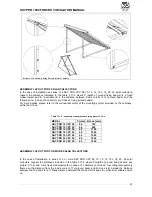
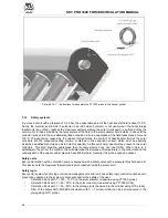
The minimum distance between the collector and the obstacle (D) in cm is given by the height of the
obstacle itself (h) in cm, per a coefficient (J), which varies according to the latitude at which the system is
installed (refer to the table)
Should the system be at a latitude that differs from those shown in the table, the following formula is used to
calculate coefficient J:
J = 1/tg(61°-L)
where:
L = latitude of the location of installation
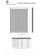
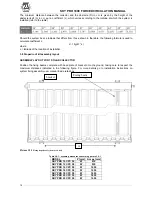
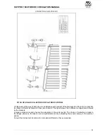
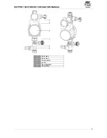
3.9 Sloped roof kit assembly layout
ASSEMBLY LAYOUT FOR 1 SOLAR COLLECTOR
Position the fixing beams complete with base plate of bracket onto the ground, taking care to respect the
maximum distances indicated in the following figure. For more details go to installation instructions on
system fixing assembly user manual inside retail box.
Picture 3.9-1
Fixing sloped roof system as a whole
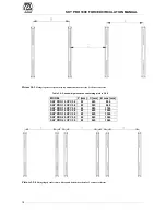
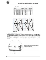
Table 3.9-1 : assembly measures concerning picture 3.9-1
MODEL
P [mm] A max [mm]
SKY PRO 10 CPC 58
W
610
SKY PRO 12 CPC 58
W
830
SKY PRO 14 CPC 58
W
1050
SKY PRO 16 CPC 58
W
1250
SKY PRO 18 CPC 58
W
1450
SKY PRO 20 CPC 58
W
1650
SKY PRO 22 CPC 58
W
1650
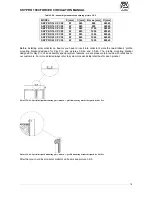
A
bracket
Fixing beam
Summary of Contents for SKY PRO 10 CPC 58
Page 1: ...TECHNICAL MANUAL SOLAR COLLECTORS SKY PRO 1800 ...
Page 2: ......
Page 47: ...SKY PRO 1800 FORCED CIRCULATION MANUAL C C 47 ...
Page 49: ......


