KTR-STOP
®
M-A-F B-xx
Operating/Assembly instructions
KTR-N
Sheet:
Edition:
445145 EN
7 of 23
1
Please observe protection
note ISO 16016.
Drawn:
2022-12-20 Ka/Wie
Replacing:
Verified:
2022-12-21 Ka
Replaced by:
The brake is supplied in pre-assembled condition. Before assembly the brake has to be inspected for completen-
ess.
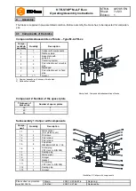
Components/subassemblies of brake
– Type M-A-F B-xx
Compo-
nent/sub-
assembly
Quantity
Description
1
1
Caliper with components
2
1)
Distance plate
3
1
Base plate with
guide pin
4
2
Centering system
5
2
Pad retraction set movable
side
6
2
Brake pad
7
2
Pad retraction set on fixed
side
8
1
2)
Sensor
1) Number depends on thickness of brake disk.
2) Optionally available
Illustration 4: Components/subassemblies of brake
Component 2: Number of the spacer plate
Thickness of
brake disk
Number of spacer plates
30
2
40
1
50
-
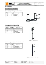
Subassembly 1: Caliper with components
Compo-
nent
Quantity
Description
Illustration 5: Caliper with components
1.1
1
Brake caliper
(incl. piston cover)
1.2
4
DU sleeve
1.3
2
Pad retainer
1.4
2
Pad retainer
1.5
8
Cap screw
DIN EN ISO 4762 - 10.9
1.6
4
Screw plug
VSTI (acc. to DIN 908)
1.7
1
Sealing plug
1.8
1
Brake piston
1.9
1
Scraper
1.10
1
Gasket
1.11
1
Screw plug
VSTI (acc. to DIN 908)
1.12
1
Sealing plug
1.13
4
Scraper
4
Assembly
4.1 Components of the brake


