KTR-STOP
®
M-A-F B-xx
Operating/Assembly instructions
KTR-N
Sheet:
Edition:
445145 EN
18 of 23
1
Please observe protection
note ISO 16016.
Drawn:
2022-12-20 Ka/Wie
Replacing:
Verified:
2022-12-21 Ka
Replaced by:
!
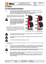
Please make sure that at least one screw plug (component 1.6) is removed when moving
back the brake piston. Afterwards re-assemble the screw plug.
•
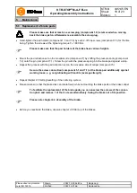
Hand-tighten the pad holders (component 1.3 and 1.4) by each 2-off cap screws (component 1.5) for the time
being. Tighten the screws at the tightening torque T
A
= 890 Nm.
Please make sure that the pad holders of the brake have various heights.
•
Mount the pad retraction set on the movable side (component 7) by shifting the pressure spring (component
7.2) onto the pin (component 7.1). Screw the pin with the pressure spring into the brake pad against a stop.
•
Repeat this process with the pad retraction set on the moveable side of caliper (component 5).
Secure the screw connection (component 5.1 and 7.1) at the brake pad additionally against
working loose, e. g. conglutinating with Loctite (average strength).
•
Repeat chapter 4.5
Setting/resetting of the centering system
.
•
Please make sure that the brake disk can rotate freely while not touching the brake pads or the brake caliper.
To facilitate the replacement of the brake pads you can unscrew the screws of the connec-
tion plate and remove 1 of the 2 screws alternatively. Swing the brake out of its position.
Please note chapter 4.4 Assembly of the brake.
•
Before you reactivate the brake, observe chapter 4.8 Start-up of the brakes.
5
Maintenance
5.1 Replacement of brake pads


