background image

20 


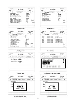
Output data                                                                    Modules data 


Detailed module data                                                                  Input data 


Battery data                                                                    Status data 


Command data                                                                    Setting data1 


      30KVA                                                          22-12-2008 
ID:01                                                                      08:30 

◄ 

Output 

Module 

Input 

Batt 

State 

► 

                                                                A 
Phase Voltage(v)                                  220 
Phase Current(A)                                    1 
Frequency(H

Z

)                                     


50 

Active Power(kw)                         


    0.0 

Apparent Power(KVA)                       


0.0 

Load percent(%)                                 


  0 

Load crest factor                                    0.0 


      30KVA                                                          22-12-2008 
ID:01                                                                      08:30 

◄ 

Output 

Module 

Input 

Batt 

State 

► 

Module01        Non-Output 
Module02        Non-Output 
Module03        Non-Output 
Module04        Non-Output 
Module05        Non-Output 
Module06        Non-Output 
Module07        Non-Output 
Module08        Non-Output 
Module09        Non-Output 
Module10        Non-Output 


      30KVA                                                        22-12-2008 
ID:01                                                                      08:30 

◄ 

Output 

Module 

Input 

Batt 

State 

► 


Module01                                       

  Invert Voltage(V)                                  220 
  Invert Current(A)               


                0 

  Frequency(HZ)                                      50 
  Positive Bus Voltage(V)                          360 
  Negative Bus Voltage(V)                        360 
  Code                    8000-8000                          D800-8000 


0000-0000                          0000-0000 

 
                                                                                          Back 


      30KVA                                                        22-12-2008 
ID:01                                                                      08:30 

◄ 

Output 

Module 

Input 

Batt 

State 

► 

Mains                                          A            B                C 

  Phase Voltage(V)                          220          220            220 
  Phase Current(A)                     


2              2                2 

  Frequency(HZ)                           


  50 

  Power Factor                       


    0.99     


  0.99       


    0.99 

      Bypass 
  Phase Voltage(V)                 


    220     


  220       


  220 

  Frequency(HZ)                              50 


      30KVA                                                          22-12-2008 
ID:01                                                                      08:30 

◄ 

Output 

Module 

Input 

Batt 

State 

► 

 
Positive Battery Voltage (V)                                240.0 
Negative Battery Voltage (V)                              240.0 
Positive Battery Current (A)                                10.0 
Negative Battery Current (A)                             


10.0 

Battery State                                                        Charge 
Battery Temperature (

)                                        28 

Lasting(min)                                                           


90 


      30KVA                                                          22-12-2008 
ID:01                                                                      08:30 

◄ 

Output 

Module 

Input 

Batt 

State 

► 

 
Input Switch                                            ON 
Output Switch                                       


ON 

Bypass Switch                                          Invalid 
Manu-Bypass Switch                             


OFF 

Inside Temperature (

)                       


30 


      30KVA                                                          22-12-2008 
ID:01                                                                      08:30 

◄ 


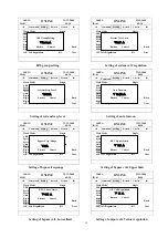
Setting 

Record 

Version 

► 


Battery Test 

    Buzzer Set                        Mute 
    Default Set 


      30KVA                                                          22-12-2008 
ID:01                                                                      08:30 

◄ 


Setting 

Record 

Version 

► 

                Language 
      Change Password 
      Date Setting                          2008-12-22 08:30:00 
      Back-Light Delay                        10Min 
      Contrast                                      20 
      Self-Test Date                        STA 18:36 


FOR:60min            Back 

      Timing of ON/OFF             


ON:MON 08:48 


OFF:SUN 17:25 


  Next 


ONLINE 

ONLINE 

ONLINE 

ONLINE 

ONLINE 

ONLINE 

ONLINE 

ONLINE 


Command


Command


Summary of Contents for YDC9300-RT Series

Page 1: ......

Page 2: ...ency online UPS designed by our R D team who is with years of designing experiences on UPS With excellent electrical performance perfect intelligent monitoring and network functions smart appearance c...

Page 3: ...y connection 12 3 10 Online UPS Modules Replacement 13 4 Operation 15 4 1 Operation Modes 15 4 2 Turn on off UPS 15 4 2 1 Restart procedure 15 4 2 2 Test procedure 17 4 2 3 Black Cold start procedure...

Page 4: ...strongly poisonous and do harmful to body 4 Please avoid short circuit between anode and cathode of battery otherwise it will cause spark or fire 5 Don t disassemble the UPS cover or there may be an...

Page 5: ...h 50KVA as maximum and vice versa so the 2M cabinet for 10 modles can reach max 100KVA N X parallel redundancy This series UPS adopts N X parallel redundancy design user can set different redundancy a...

Page 6: ...g 1 Don t lean the UPS when moving it out from the packaging 2 Check the appearance to see if the UPS is damaged or not during the transportation do not switch on the UPS if any damage found Please co...

Page 7: ...in Switch for UPS Module 2 19 Main Switch for UPS Module 3 20 Main Switch for UPS Module 4 21 Main Switch for UPS Module 5 22 Cover for terminal block 23 Inter connecting port for Modules 24 Dry Conta...

Page 8: ...6 2 2M 19 Rack Cabinet Front View Side View Rear View 1 front lock 2 LCD Display 3 Side Lock 4 Rear Lock 1 2 2 3 2 2 2 4 2...

Page 9: ...in Switch for UPS Module 2 24 Main Switch for UPS Module 3 25 Main Switch for UPS Module 4 26 Main Switch for UPS Module 5 27 Main Switch for UPS Module 6 28 Main Switch for UPS Module 7 29 Main Switc...

Page 10: ...4 fan 5 UPS Module input switch 3 4 UPS Module LCD control panel LCD control panel introduction 1 LCD Display Board 2 ESC 3 Off button 4 On button 5 right or down 6 Enter 7 left or up 8 Output Indicat...

Page 11: ...thin the required specs Temperature is a major factor in determining battery life and capacity In a normal installation the battery temperature is maintained between 15 C and 25 C Keep batteries away...

Page 12: ...Over current Protection device shall be installed at the distribution panel of the incoming main supply It may identify the power cables current capacity as well as the overload capacity of the syste...

Page 13: ...ut N GND Cable diameter 75mm2 35mm2 The 100KVA Item Input three phases Battery Output Single phase Ground Symbol Vin N Vin A Vin B Vin C BAT BATN BAT Vout L Vout N GND Cable diameter 150mm2 Or 2 75mm2...

Page 14: ...e input Line BAT BATN and BAT are connected to the external battery box output L N are connected to the equipment load which is supplied by the UPS WARNING If the load equipment is not ready to accept...

Page 15: ...current could be adjusted automatically according to battery capacity selected Also charger current is selectable Please refer to Chapter 4 3 LCD display CAUTION Ensure correct polaritybattery string...

Page 16: ...matically and parallel up the modules into whole system Remove UPS module Remove the coronal screws on the left side of the module to stop the module running completely and remove the module after fan...

Page 17: ...he inverter supply to bypass supply without interruption to the critical load In the event that the inverter output is not synchronized with the bypass AC source the static switch will perform a trans...

Page 18: ...wer switch must be OFF Turn ON the input switches of all UPS modules which locate at the modules rear panels When AC MAINS input voltage within the range the MAINS LED of the UPS modules will light up...

Page 19: ...mum capacity during load test 4 2 3 Black Cold start procedure CAUTION Follow these procedures when the input AC Utility Failure but battery is normal Turn on the battery switch The battery will feed...

Page 20: ...o the main power switches Switch ON the output breakers of the modules Switch ON the input breakers of the modules The UPS powers from the static bypass instead of the maintenance bypass then the bypa...

Page 21: ...ted to advise service personnel that the UPS circuit is under maintenance WARNING Wait for about 5 minutes for the internal D C bus bar capacitors to be completely discharged 4 3 The Display 4 3 1 Sys...

Page 22: ...A 22 12 2008 ID 01 08 30 Output Module Input Batt State Mains A B C Phase Voltage V 220 220 220 Phase Current A 2 2 2 Frequency HZ 50 Power Factor 0 99 0 99 0 99 Bypass Phase Voltage V 220 220 220 Fre...

Page 23: ...Base Volt 2 25 Battery Protect Volt 1 70 Boost Charge Enable Back Boost Last Time 231 Min Max Charge Current 25A Next 30KVA 22 12 2008 ID 01 08 30 Setting Record Version 0001 12 21 15 00 26 On Line 0...

Page 24: ...Next 30KVA 22 12 2008 ID 01 08 30 Setting Record Version Language Change Password Date Setting 2008 12 22 08 30 00 Back light Delay 10Min Contrast 20 Self Test Date STA 18 36 FOR 60min Back Timing of...

Page 25: ...0 Next 30KVA 22 12 2008 ID 01 08 30 Setting Record Version Work Mode Single LBS Group Setting Master System Voltage Level 220V System Frequence Level 50HZ Auto Turn on Enable Bypass Frequence Range 2...

Page 26: ...30KVA 22 12 2008 ID 01 08 30 Setting Record Version Parallel ID 01 M S Alternate Cyc 6 M UPS Output Ena Pre Alarm Time 14 Float Volt Revise 0 00 Parallel Amount 04 Parallel Redundancy 01 Back Next 30...

Page 27: ...0 Setting Record Version Single Battery Volt 12V Battery Number 20 Battery Group 1 Single Battery Capa 100AH Boost Upper Limit Volt 2 31 Float Base Volt 2 25 Battery Protect Volt 1 70 Boost Charge Ena...

Page 28: ...he details by pressing them 5 Select and confirm the data information can view the details It contains the details of the AC input output inverter battery BUS parallel and temperature Shown as the pic...

Page 29: ...and system setting Shown as the picture below setting menu 8 Select and confirm client setting then you may set the following User setting information Figure Invert 220 0V 50 0HZ Figure PBatt Dischar...

Page 30: ...er inverter static bypass and battery operation 3 MAINS INDICATOR LED the status of the AC Input 4 INVERT INDICATOR LED the status of the inverter 5 OUTPUT INDICATOR LED the status of the output 6 BYP...

Page 31: ...arity Reversed charger abnormal Off Battery and Converter Normal Battery charging Bypass indicator Green Load on Bypass power Flashing Green Bypass not available out of normal range Static bypass swit...

Page 32: ...ifier Current Limit When the input voltage is at 208V 305V the output of the UPS will not be interrupted but it will be at current limit for example to reduce charge current When the load connected ex...

Page 33: ...d module is removed Alarm Information No Display message Meaning 1 Rectifier Fault Rectifier detected faulty Rectifier and inverter and charger shut down 2 Rectifier Over Temperature The temperature o...

Page 34: ...system load sharing fault If any unit in a parallel system has an unbalance load share that exceeds 30 this warning will occur 31 Bypass Site Wiring Fault Wrong phase rotation on the bypass side 32 S...

Page 35: ...del set wrong Model setting of the UPS is incorrect 4 5 Options Network Management Card with Environmental Monitoring CAUTION For network management configuration and use refer to the separate user ma...

Page 36: ...ages and is setup for web based auto language detection Typical topology of the UPS Network Management Relay card A 10 pin terminal is supported to offer the signals of Bypass Utility Failure Inverter...

Page 37: ...4Wires Ground or 1Phase 2 Wires Ground Rated Voltage 380 400Vac or 220 230VAC Voltage Range 208 478Vac or 120VAC 276VAC Frequency Range 40 70Hz Power Factor 0 99 Bypass Voltage Range Max voltage 15 op...

Page 38: ...atteries Operating Environment Temperature 0 40 Humidity 0 95 non condensing Storage temperature 25 55 Altitude 1500m Other Unit Dimensions W D H UPS cabinet 600 840 1400mm 600 840 2000mm UPS module 4...

Page 39: ...D E F 4 5 6 7 C D E F 2 3 6 7 A B C E F 1 3 5 7 9 B D F BBBB BBBB Inverter State Byte 1 8 9 A B C D E F Int bypass Switch Closed 4 5 6 7 C D E F Int output Switch Closed 2 3 6 7 A B C E F Manu Bypass...

Page 40: ...re 2 3 6 7 A B C E F Inverter over temperature 1 3 5 7 9 B D F Rectifier over current 8 9 A B C D E F Auxiliary power 1 fault 4 5 6 7 C D E F Auxiliary power 2 fault 2 3 6 7 A B C E F Input Thyristor...

Page 41: ...D E F Bypass Thyristor short 4 5 6 7 C D E F Bypass Thyristor broken 2 3 6 7 A B C E F CAN comm Fault 1 3 5 7 9 B D F Parallel load sharing fault Byte 2 8 9 A B C D E F Bypass Site Wiring Fault 4 5 6...

Page 42: ...active signal from monitoring board IO 2 3 6 7 A B C E F battery monitoring system connected 1 3 5 7 9 B D F system unregistered FF Monitoring Byte 1 8 9 A B C D E F Battery Falut from battery monito...

Page 43: ...not powered ON Input power supply is not connected Input voltage low The input swith of the module is not switched on measure if the UPS input voltage frequency are within the window Check if all mod...

Page 44: ...The UPS output is in short circuit Make sure the load is not in short circuit then restart the UPS 12 The LED of the Module with RED light The module is not inserted properly Pull out the module and i...

Page 45: ...S232 port UPS RS232 port Pin 2 Pin 2 UPS send PC receive Pin 3 Pin 3 PC send UPS receive Pin 5 Pin 5 ground Available function of RS232 Monitor UPS power status Monitor UPS alarm info Monitor UPS runn...

Reviews: