background image

15 

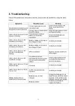
3-6 Alarm or Fault reference code 


Event log   

UPS Alarm Warning 

Buzzer 

LED 

Rectifier Fault 

Beep continuously 

Fault LED lit 

Inverter 

fault(Including 

Inverter 

bridge is shorted) 

Beep continuously 

Fault LED lit 

Fan fault 

Beep continuously 

Fault LED lit 

12 

Selftest fault 

Beep continuously 

Fault LED lit 

13 

Battery Charger fault 

Beep continuously 

Fault LED lit 

15 

DC Bus over voltage 

Beep continuously 

Fault LED lit 

16 

DC Bus below voltage 

Beep continuously 

Fault LED lit 

17 

DC bus unbalance 

Beep continuously 

Fault LED lit 

18 

Soft start failed 

Beep continuously 

Fault LED lit 

19 

UPS Inside Over Temperature 

Twice per second 

Fault LED lit 

20 

Heatsink Over Temperature 

Twice per second 

Fault LED lit 

26 

Battery over voltage 

Once per second 

Fault LED blinking 

29 

Output Short-circuit 

Once per second 

Fault LED blinking 

30 

Input current limit 

Once per second 

Fault LED blinking 

31 

Bypass over current 

Once per second 

BPS LED blinking 

32 

Overload 

Once per second 

INV 

or 

BPS 

LED 

blinking 

33 

No battery 

Once per second 

Battery LED blinking 

34 

Battery under voltage 

Once per second 

Battery LED blinking 

35 

Battery low pre-warning 

Once per second 

Battery LED blinking 

36 

Over load time out 

Once per 2 seconds


Fault LED blinking 

37 

DC component over limit. 

Once per 2 seconds


INV LED blinking 

39 

Mains volt. Abnormal 

Once per 2 seconds 

Battery LED lit 

40 

Mains freq. abnormal 

Once per 2 seconds 

Battery LED lit 

41 

Bypass Not Available 


BPS LED blinking 

42 

Bypass unable to trace 


BPS LED blinking 

43 

Inverter on invalid 


44 

Not at Inverter side 


Summary of Contents for UDC9100 Series

Page 1: ...out high frequency online UPS designed by our R D team who is with years of designing experiences on UPS With excellent electrical performance perfect intelligent monitoring and network functions smart appearance complying with EMC and safety standards The UPS meets the world s advanced level Read this manual carefully before installation This manual provides technical support to the operator of t...

Page 2: ... this guide 4 2 Installation and setup 4 2 1 Unpack checking 4 2 2 Real panel view 4 2 3 LCD control panel 6 2 4 Setup the UPS 6 3 Operations 8 3 1 Button operation 8 3 2 LCD display 9 3 3 UPS setting 11 3 4 Operating Mode Description 14 3 5 Operational Status and Mode s 14 3 6 Alarm or Fault reference code 15 4 Troubleshooting 16 5 Storage and Maintenance 17 6 Specification 18 ...

Page 3: ...ent The UPS system must be absolutely dry before being installed Please allow at least two hours for the UPS system to acclimate the environment Do not install the UPS system near water or in moist environments Do not install the UPS system where it would be exposed to direct sunlight or near heater Do not block ventilation holes in the UPS housing 1 3Installation Do not connect appliances or devi...

Page 4: ...ries and verify that no current is present and no hazardous voltage exists in the terminals of high capability capacitor such as BUS capacitors Only persons are adequately familiar with batteries and with the required precautionary measures may replace batteries and supervise operations Unauthorized persons must be kept well away from the batteries Caution risk of electric shock The battery circui...

Page 5: ...lease keep the original package in a safe place for future use 2 1Unpack checking Don t lean the UPS when moving it out from the packaging Check the appearance to see if the UPS is damaged or not during the transportation do not switch on the UPS if any damage found Please contact the dealer right away Check the accessories according to the packing list and contact the dealer in case of missing pa...

Page 6: ...5 2KVA S 2KVA H 3KVA H 3KVA S ...

Page 7: ...inal 10 Output Terminal 2 3LCD control panel LCD control panel introduction 1 LED from top to bottom alarm bypass battery inverter 2 LCD display 3 Selectbutton enter to next item 4 Off button 5 On button 2 4Setup the UPS Step 1 UPS input connection Plug the UPS into a two pole three wire grounded receptacle only Avoid using extension cords For 200 208 220 230 240VAC models The power cord is suppli...

Page 8: ...are installed you can schedule UPS shutdown start up and monitor UPS status through PC The UPS is equipped with intelligent slot perfect for either SNMP or Relay card When installing either SNMP or Relay card in the UPS it will provide advanced communication and monitoring options NOTE USB port and RS 232 port can t work at the same time Step 4 Turn on the UPS Press the ON button on the front pane...

Page 9: ... is normal press and hold this button for 2 seconds Then UPS will enter to bypass mode This action will be ineffective when the input voltage is out of acceptable range Up key Press this button to display previous selection in UPS setting mode Select Mute Button Switch LCD message Press this button to change the LCD message for input voltage input frequency battery voltage output voltage and outpu...

Page 10: ...9 3 2LCD display There are 8 interfaces available in the LCD display Item Interface Description Content Displayed 01 Input voltage 02 Battery voltage 03 Output voltage ...

Page 11: ...10 04 Load 05 Temperature Environment Temperature Heatsink Temperature 06 Firmware Version UPS model ...

Page 12: ...n as below while the charger is on 3 3UPS setting The setting fuction is controled by 3 buttons Enter Select Off up On down Enter Off up goes into the setting page Enter value adjustment Off On for choosing different pages After the UPS turn ON press buttons for 5seconds and then goes into the setting interface page Note Figure at left corner is the page number of the setting pages ...

Page 13: ... 127 or 200 208 220 230 240 Press UP button to select the previous setting Press DOWN button to select the next setting 03 Frequency setting Press select button to change the setting 50 or 60Hz Press UP button to select the previous setting Press DOWN button to select the next setting 04 Battery capacity setting Press select button to change the setting Battery capacity range is 1 200Ah Press UP b...

Page 14: ...elect the next setting 06 Bypass voltage lower limit setting Press select button to change the setting The bypass voltage lower limit range is 170 220Vac Press UP button to select the previous setting Press DOWN button to select the next setting 07 Mute setting Press select button to change thesetting ON or OFF Press UP button to select the previous setting Press DOWN button to save and exit the s...

Page 15: ...the acceptable range or power failure and alarm is sounding every 4 second UPS will backup power from battery Battery led light Standby mode UPS is powered off and no output supply power but still can charge batteries All LEDs turn off Bypass mode When input voltage is within acceptable range but UPS is overload UPS will enter bypass mode or bypass mode can be set by front panel Bypass led light 3...

Page 16: ...ture Twice per second Fault LED lit 26 Battery over voltage Once per second Fault LED blinking 29 Output Short circuit Once per second Fault LED blinking 30 Input current limit Once per second Fault LED blinking 31 Bypass over current Once per second BPS LED blinking 32 Overload Once per second INV or BPS LED blinking 33 No battery Once per second Battery LED blinking 34 Battery under voltage Once...

Page 17: ...aler Alarm code is shown as 34 and battery led blinking Battery voltage is too low or the charger is fault Contact your dealer Alarm code is shown as 32 and INV or BYPASS led blinking UPS is overload Remove excess loads from UPS output Alarm code is shown as 29 and FAULT led light The UPS shut down automatically because short circuit occurs on the UPS output Check output wiring and if connected de...

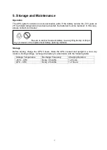
Page 18: ...aler Storage Before storing charge the UPS 5 hours Store the UPS covered and upright in a cool dry location During storage recharge the battery in accordance with the following table Storage Temperature Recharge Frequency Charging Duration 25 C 40 C Every 3 months 1 2 hours 40 C 45 C Every 2 months 1 2 hours Be sure to deliver the spent battery to a recycling facility or ship it to your dealer in ...

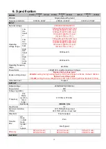
Page 19: ...ncy range 40 70Hz Power factor 0 99 100 load Nominal Input Voltage Bypass voltage range Bypass high voltage point 230 264 setting the high voltage point in LCD from 230Vac to 264Vac Default 264Vac Bypass low voltage point 170 220 setting the low voltage point in LCD from 170Vac to 220Vac Default 170Vac Generator input Support OUTPUT Output voltage 200 208 220 230 240Vac Power factor 0 9 Voltage re...

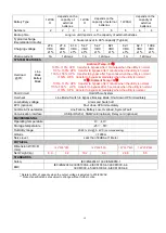
Page 20: ...PS transfer to bypass after 1minute when the utility is normal 110 130 UPS transfer to bypass after 5 seconds when the utility is normal 130 UPS transfer to bypass immediately when the utility is normal Short Circuit Hold Whole System Overheat Line Mode Switch to Bypass Backup Mode Shut down UPS immediately Low battery voltage Alarm and Switch off EPO optional Shut down UPS immediately Audible Vis...

Reviews: