


5 Installation at Site
13 of 20
M 1 (K) Alarm Contactor
M1
734
720.02
81-45
4
6
0
m
m
732.02
733
550
900
920
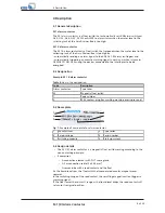
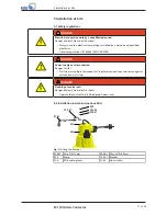
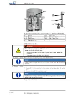
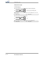
Fig. 5:
Installation drawing of M 1 (K) alarm contactor in Ama-Drainer-Box 1U/1B
550
Disc
720.02 Anti-rotation device
732.02 Bracket
733
Clamp
734
M 16 cable gland
81-45
Float switch
900
Cheese head screw
920
Hexagon nut
M1
Drilled hole, Ø 16 mm
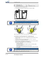
5.4 Installation in Ama-Drainer-Box Z2 U/Z2 B - dual-pump units
1.
Fasten float switch 81-45 to bracket 732.02 (width across flats 17); see alarm
contactor M 1 (K) installation drawing below.
2.
Fasten the pre-assembled bracket with float switch to cross beam 573 using
cheese head screws 900, discs 550, and hexagon nuts 920.
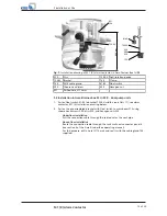
–
Underfloor installation
Pull the connection cable through the cable duct or the vent pipe.
–
Above-floor installation
Route the connection cable through the tank wall near connector panel 6
(see section 9 of the Ama-Drainer-Box operating manual).
For this purpose, drill a hole (Ø 16 mm) and seal it with the cable gland 734
supplied.